Threading tube coupler of wind generating set
A technology for wind power generating sets and threading pipes, which is applied in the direction of wind power generator components, wind power engines, couplings, etc., and can solve the problem of center deviation, unfavorable disassembly of the coupling for the input shaft of the generator and the output shaft of the gearbox, There are no problems such as the centering effect, and the effects of good centering effect, twist prevention, and convenient installation and disassembly are achieved.
- Summary
- Abstract
- Description
- Claims
- Application Information
AI Technical Summary
Problems solved by technology
Method used
Image
Examples
Embodiment 1
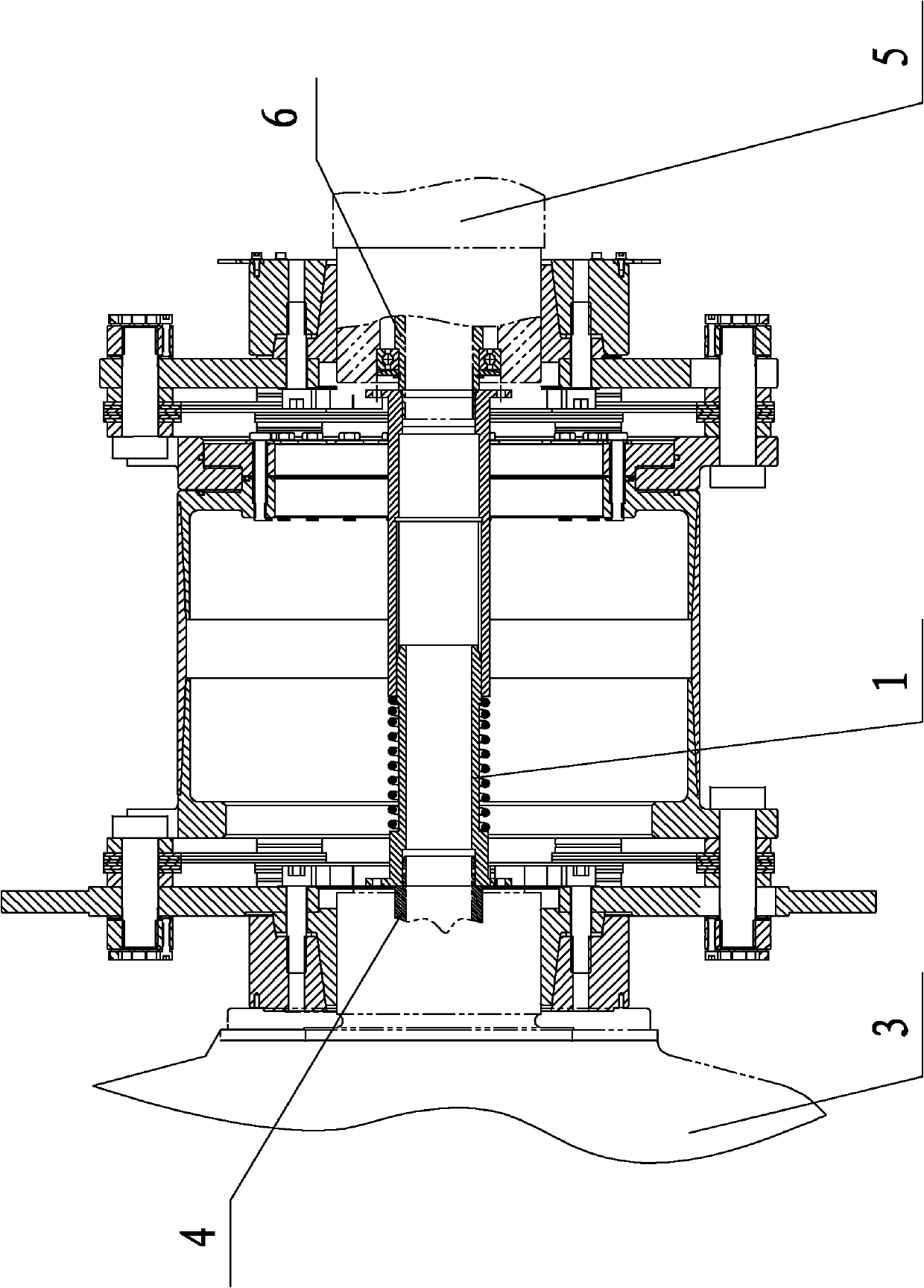
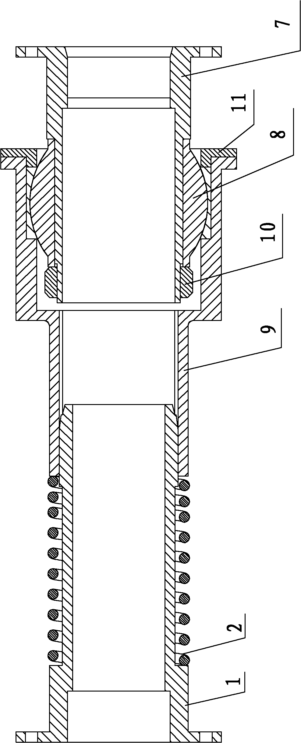
[0020] Embodiment one: if figure 1 figure 2 As shown, a threading pipe coupling for a wind power generating set has a left joint 1, a spring 2, and a right partial joint. Both the left joint 1 and the right partial joint have hollow cavities inside, and the front end of the left joint 1 is connected to the right partial joint. The rear end is connected by clearance fit. The outer circumference of the left joint 1 has a stepped card slot. The spring 2 is installed in the stepped card slot. The blocking surface at the front end of the stepped card slot is lower than the blocking surface at the rear end. On the blocking surface of the rear end of the type card slot, the other end of the spring 2 is against the end face of the rear end of the right part of the joint, a sliding key is provided on the outer circumference of the front end of the left joint 1, and a sliding key is provided on the inner peripheral surface of the right part of the joint. Fitted keyway.
[0021] The i...
Embodiment 2
[0023] Embodiment two: if image 3 Figure 4 As shown, a threading pipe coupling of a wind power generating set, the right part of the joint includes a bearing seat 9 and a right end joint 7, and the inside of the right end joint 7 has a sixth cavity connected to the second threading pipe joint 6 of the input shaft of the generator 5 And the seventh cavity for placing the line pipe, the outer circumference of the right end joint 7 has the first step, the second step, and the third step that decrease in turn, and the joint bearing 8 is installed on the second step, and the joint bearing 8 is formed by the nut 10 Locked on the right end joint 7, the front end of the bearing seat 9 has a gland 11, and the gland 11 presses the joint bearing 8.
[0024] The bearing seat 9 has an eighth cavity for clamping the joint bearing 8, a ninth cavity for placing the nut 10 and a threading pipe, and a tenth cavity for clearance fit with the front end of the left joint 1. The bearing The out...
PUM
 Abstract
Description
Claims
Application Information
 - R&D
- Intellectual Property
- Life Sciences
- Materials
- Tech Scout
- Unparalleled Data Quality
- Higher Quality Content
- 60% Fewer Hallucinations
Browse by: Latest US Patents, China's latest patents, Technical Efficacy Thesaurus, Application Domain, Technology Topic, Popular Technical Reports.
© 2025 PatSnap. All rights reserved.Legal|Privacy policy|Modern Slavery Act Transparency Statement|Sitemap|About US| Contact US: help@patsnap.com


