Oil pump for chain saw

A chain saw and oil pump technology, applied in chainsaws, sawing equipment, sawing machine devices, etc., can solve the problems of easy blockage of oil outlets, waste of resources, easy oil leakage, etc., to improve service life, uniform oil output, Energy saving effect

Active Publication Date: 2013-06-12
ZHEJIANG YAT ELECTRICAL APPLIANCE CO LTD
View PDF7 Cites 0 Cited by
  • Summary
  • Abstract
  • Description
  • Claims
  • Application Information

AI Technical Summary

Problems solved by technology

At present, there are mainly plunger oil pumps, worm gear oil pumps, and manual oil pumps on the market. However, during the use of chain saws, debris such as wood chips can easily block the oil outlet, causing the oil pump to not produce oil. In the violent vibration environment during work, the oil pump is easy to shift due to the unstable fixing method, and even collides with the transmission mechanism or the saw chain to cause damage
[0003] A utility model patent named chain saw was authorized and announced by the State Intellectual Property Office of China on February 11, 2009. The authorized announcement number is CN201192009Y. The patent specification discloses a chain saw, including an oil supply device. The oil supply device includes For the oil pump, the cam linked by the transmission mechanism interferes with the plunger of the oil pump to realize the reciprocating motion of the plunger to pump oil. Although this structure uses the kinetic energy of the transmission mechanism to realize the reciprocating movement of the oil pump plunger, the cam structure does not Stable and inaccurate, it is easy to cause irregular reciprocating motion of the plunger, which will cause uneven changes in the pressure in the oil pump and the pump oil volume, and oil leakage will easily occur, which not only causes waste of resources, but also affects the use of users and affects the environment. There is also a certain degree of pollution

Method used


Image

  • Oil pump for chain saw
  • Oil pump for chain saw
  • Oil pump for chain saw

Examples


Embodiment Construction

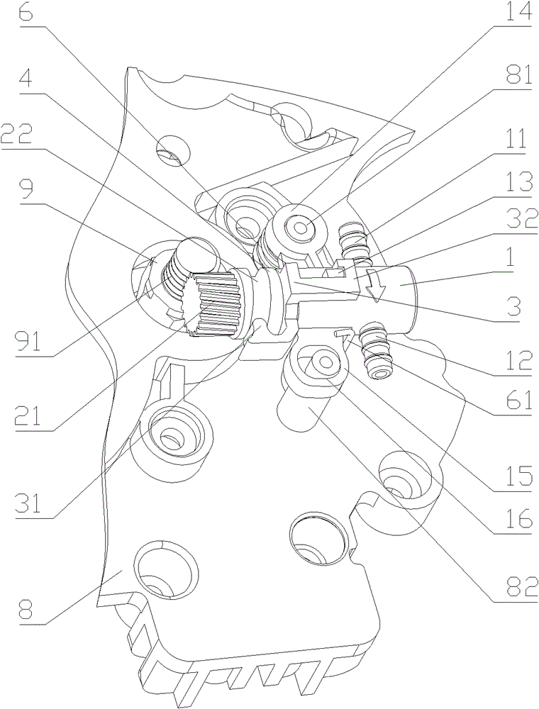
[0018] Such as Figures 1 to 3 Shown is a structural schematic diagram of an embodiment of the present invention, an oil pump for a chainsaw, including a pump body 1 arranged on a chainsaw support plate 8, the pump body is provided with an oil inlet 11 and an oil outlet 12, and the pump body There is a piston rod 2 that moves horizontally reciprocating relative to the pump body. A transmission mechanism is provided between the front end of the piston rod and the shaft head of the chainsaw output shaft 9 to make the piston rod rotate with the output shaft. There is a rotating guide structure between the pump bodies to make the piston rod reciprocate horizontally relative to the pump body when it rotates.

[0019] The transmission mechanism is an meshing transmission mechanism, which includes a worm wheel 21 arranged at the front end of the piston rod and a worm 91 arranged at the shaft head of the chainsaw output shaft to mesh with the worm wheel, and the said worm is arranged ...


PUM


Abstract

The invention discloses an oil pump for a chain saw, which comprises a pump body arranged on a chain saw supporting plate, wherein the pump body is provided with an oil inlet and an oil outlet, the pump body is internally provided with a piston rod reciprocating relative to the pump body, a transmission mechanism is arranged between the front end of the piston rod and a shaft head of a chain saw output shaft to ensure that the piston rod rotates with the output shaft, and a rotary guide structure is arranged between the piston rod and the pump body to ensure that the piston rod horizontally reciprocates relative to the pump body during the rotation. The invention has a simple, reasonable, reliable and practical structure, and is energy-saving and environmental-friendly; and control accuracy of a piston of the oil pump is improved and stability of oil pumping capacity of the oil pump is enhanced.

Description

technical field [0001] The invention relates to a lubricating oil pump, in particular to an oil pump for a chain saw. Background technique [0002] Chain saws are widely used in households, gardens, forests and other fields. When the chain saw is working, the transmission mechanism and the saw chain are running at high speed. Due to the friction will generate a lot of heat, it needs to be lubricated in time to prevent the saw chain from overheating. The chainsaw is damaged or even the user is injured. At present, there are mainly plunger oil pumps, worm gear oil pumps, and manual oil pumps on the market. However, during the use of chain saws, debris such as wood chips can easily block the oil outlet, causing the oil pump to not produce oil. Under the severe vibration environment during work, the oil pump is easy to shift due to the unstable fixing method, and even collides with the transmission mechanism or the saw chain to cause damage. [0003] A utility model patent nam...

Claims


Application Information

Patent Timeline
Patent Type & Authority Patents(China)
IPC IPC(8): B27B17/00B23D57/02
Inventor 韩焕忠
Owner ZHEJIANG YAT ELECTRICAL APPLIANCE CO LTD
Why Eureka
Try Eureka