
Suction filtration/concentration method and suction filtration/concentration device

The technology of a concentration device and a concentration tank is applied in the directions of loose filter material filter, filtration separation, filtration treatment, etc., which can solve the problems of weak adhesion strength, no shape retention of concentrated sludge, and low concentration of concentrated sludge. To achieve the effect of preventing re-dissolution

Inactive Publication Date: 2011-08-17
METAWATER CO LTD
View PDF2 Cites 1 Cited by
  • Summary
  • Abstract
  • Description
  • Claims
  • Application Information

AI Technical Summary

Problems solved by technology

Since the above-mentioned ejection sound and collision sound, which use the filter concentration tank as the sound source, echo in the filter concentration tank, it is easy to become additional noise.
[0008] Third, the concentrated sludge accumulated at the bottom of the filter thickening tank has no shape retention, and it is difficult to discharge the concentrated sludge to the outside
In addition, due to low-pressure suction, the concentrated concentration of the attached concentrated sludge is low, and the adhesion strength between the attached solid parts is weak

Method used


Image

  • Suction filtration/concentration method and suction filtration/concentration device
  • Suction filtration/concentration method and suction filtration/concentration device
  • Suction filtration/concentration method and suction filtration/concentration device

Examples


Embodiment

[0120] In order to confirm the effect of the present invention, the present inventors conducted a siphon-type suction filtration concentration test using a filter cloth with the sludge of a water purification plant as a target for filtration and concentration, and used the peeling pressure obtained by using water as a peeling medium as a parameter. The relationship between time and peel rate was investigated.

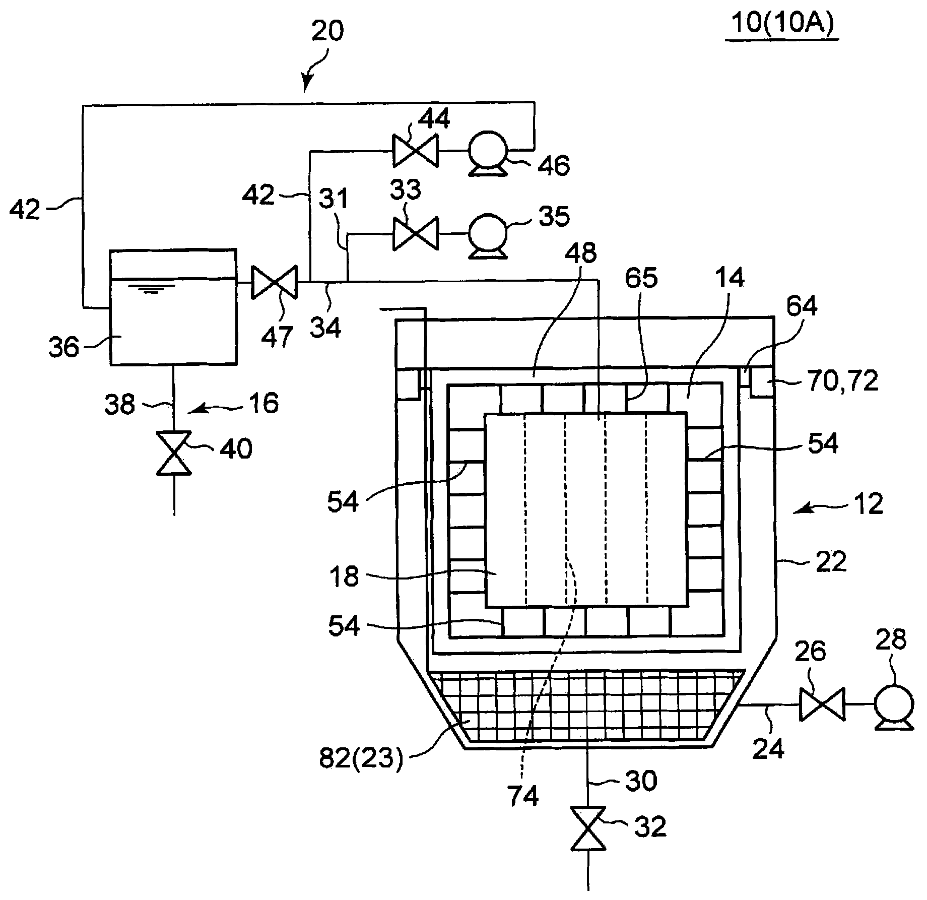
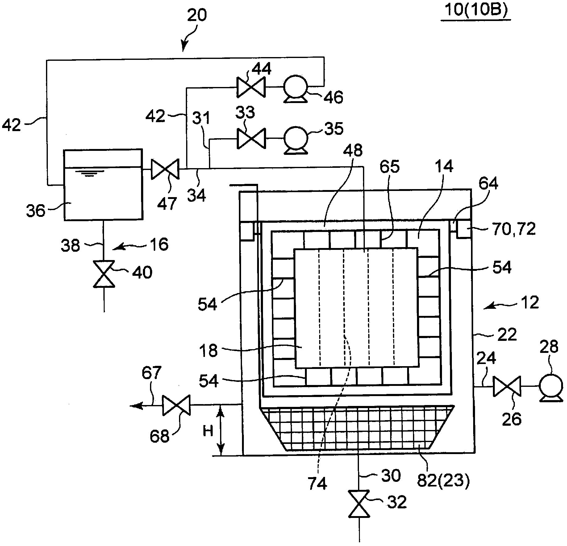
[0121] Figure 12 Indicates the entire test apparatus. Due to the basic structure and the Figure 2A The structure after removing the concentrated sludge scooping part 23 (mesh tray 82 ) is the same, so the detailed description thereof is omitted, but the water inflow pipe 42 is connected in the middle of the inverted U-shaped pipe whose one end communicates with the filter chamber 76 . 42 is provided with a peeling pressure regulating valve 150, and by adjusting the opening degree of the peeling pressure regulating valve 150, the pressure of water and the supply time...


PUM


Abstract

The invention provides a suction filtration / concentration method which comprises a sludge supply stage in which sludge is supplied to a filtration / concentration tank, a filtration / concentration stage in which the supplied sludge is concentrated by filtration within the filtration / concentration tank, a thick-sludge separation stage in which the thick sludge obtained by the filtration / concentration is separated from the outer surface of the filter cloth, and a thick-sludge discharge stage in which the separated thick sludge is discharged outside the filtration / concentration tank, wherein the filtration / concentration stage involves a step in which the thick sludge is adhered to the outer surface of the filter cloth by continuously performing suction at a given suction pressure that enables the thick sludge to retain the shape thereof even when separated in unconcentrated sludge, and the thick-sludge separation stage involves a step in which water is continuously and forcedly sent to the filter cloth via the filtration chamber over a given period to thereby separate, in the supplied unconcentrated sludge, the thick sludge (filter cake) adherent to the outer surface of the filter cloth. A suction filtration / concentration device is provided.

Description

technical field [0001] The present invention relates to a suction filtration concentration method and a suction filtration concentration device, and more particularly, to a suction filtration concentration method and a suction filtration concentration device that can be efficiently discharged to the outside without re-dissolving concentrated sludge. Background technique [0002] At present, in the concentration step of the sludge generated when the upper water is filtered, a suction filtration and concentration device using a siphon principle and a suction pump is used. Since this suction filtration concentration apparatus has a bag-shaped filter cloth which forms a filter chamber inside, the suctioned sludge (sludge before concentration) is separated into water and concentrated sludge. That is, the water|moisture content contained in sludge passes through the many pores of a filter cloth, and is guided into a filter chamber by this, and it collect|recovers as a filtrate. I...

Claims


Application Information

Patent Timeline
Patent Type & Authority Applications(China)
IPC IPC(8): C02F11/12B01D24/46B01D29/00B01D29/11B01D29/25B01D29/37B01D29/66B01D35/22C02F11/121
CPCC02F2103/002C02F2103/32C02F11/121B01D39/08C02F1/001C02F2201/002Y02W10/20
Inventor 西尾晃田畑雅郎国谷正
Owner METAWATER CO LTD
Learn More