
Calibration method of near-infrared camera

A calibration method, near-infrared technology, is applied in the field of calibration for near-infrared cameras, and can solve problems such as non-coplanar marking points

Inactive Publication Date: 2011-08-17
SOUTH CHINA UNIV OF TECH
View PDF2 Cites 16 Cited by
  • Summary
  • Abstract
  • Description
  • Claims
  • Application Information

AI Technical Summary

Problems solved by technology

[0004] The problem to be solved by the present invention is to provide a method suitable for near-infrared camera calibration. By adopting a calibration template in which the marking points are near-infrared light-emitting points, the problem of non-coplanar marking points and unequal distance between any two adjacent points can be solved to achieve near-infrared camera calibration. Calibration of infrared cameras

Method used


Image

  • Calibration method of near-infrared camera
  • Calibration method of near-infrared camera
  • Calibration method of near-infrared camera

Examples


Embodiment Construction

[0022] In order to better understand the technical solution of the present invention, a detailed description is given below in conjunction with the accompanying drawings.

[0023] Such as figure 1 As shown, the present invention provides a method for calibrating a near-infrared camera. The calibration steps are as follows:

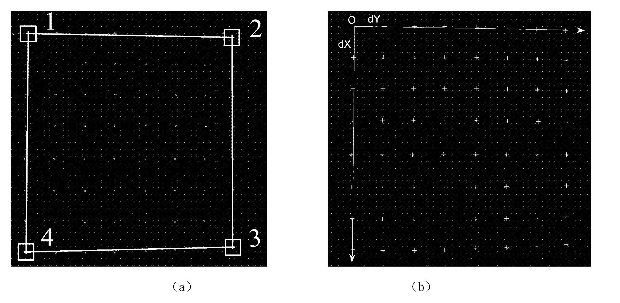
[0024] Step 1: Make a calibration board, use an 8×8 array of near-infrared light-emitting points as 64 calibration points, and add a near-infrared light-emitting point next to the calibration point in the corner of the array light-emitting area as the initial calibration point.

[0025] Step 2: Place the near-infrared calibration board within the effective field of view in front of the near-infrared camera, and adjust the camera's focal length, aperture, etc., so that the camera can clearly capture the texture of the calibration board. Then change the placement position of the calibration plate, and take a series of images at different positions. exist ...


PUM


Abstract

The invention discloses a calibration method of a near-infrared camera, which comprises the following steps of: (1) setting a calibration point in a corner of an array luminous area to be a starting calibration point by using the calibration point of a calibration plate as an array near-infrared luminous point; (2) placing the calibration plate in an effective field range of the near-infrared camera, and shooting a series of images of the calibration plate at different positions; (3) sequentially clicking the calibration points in four corners of the array luminous area according to the same direction starting from the starting calibration point on each image in a mode of mouse point-taking, extracting sub-pixel values of the four points and further extracting a sub-pixel coordinate value of each luminous point according to a position area where the luminous point on the image is located; and (4) determining a one-to-one correspondence relationship between the sub-pixel coordinate value of each luminous point and a three-dimensional coordinate point of the near-infrared calibration plate and solving internal and external parameters of the infrared camera. The calibration method can be used for high-precision calibration of the near-infrared camera, and the requirement on the calibration plate is relatively low.

Description

technical field [0001] The invention relates to camera calibration technology, in particular to a calibration method for near-infrared cameras. Background technique [0002] Camera calibration is the prerequisite for extracting 3D spatial information from 2D images, and is a key step in 3D reconstruction and stereo vision research. The calibration results directly affect the accuracy of 3D measurement and reconstruction. The essence of camera calibration is to solve the geometric model parameters of camera imaging, also known as camera internal parameters. The geometric model determines the relationship between the three-dimensional geometric position of a certain point on the surface of the space object and its corresponding point in the image. The calibration process is to use this correspondence to determine the internal parameters (geometric and optical parameters) and external parameters of the camera. The extrinsic parameters are the orientation of the camera relativ...

Claims


Application Information

Patent Timeline
IPC IPC(8): G06T7/00G06T7/80
Inventor 杨荣骞吴效明刘素娟王志刚温小艳
Owner SOUTH CHINA UNIV OF TECH
Learn More