
Tensioning transmission shaft

A transmission shaft, expansion and tightening technology, applied in the direction of couplings, rigid shaft couplings, mechanical equipment, etc., can solve the problems of large assembly force, large knocking force in disassembly, inconvenient disassembly and assembly, etc., to improve the transmission force. , to ensure the coaxiality, the effect of easy disassembly

Inactive Publication Date: 2011-08-10
ZHONGSHAN JONJEE PRECISION MACHINERY
View PDF5 Cites 5 Cited by
  • Summary
  • Abstract
  • Description
  • Claims
  • Application Information

AI Technical Summary

Problems solved by technology

When installing, you need to use a large interference fit to install, that is, you need to use a large assembly force; when disassembling, you need to use a large knocking force, which is inconvenient to disassemble
Especially in small products with high coaxiality requirements, when using keys or pins to ensure product strength, the transmission torque will be greatly reduced, reducing the scope of application of the product

Method used


Image

  • Tensioning transmission shaft
  • Tensioning transmission shaft
  • Tensioning transmission shaft

Examples


Embodiment Construction

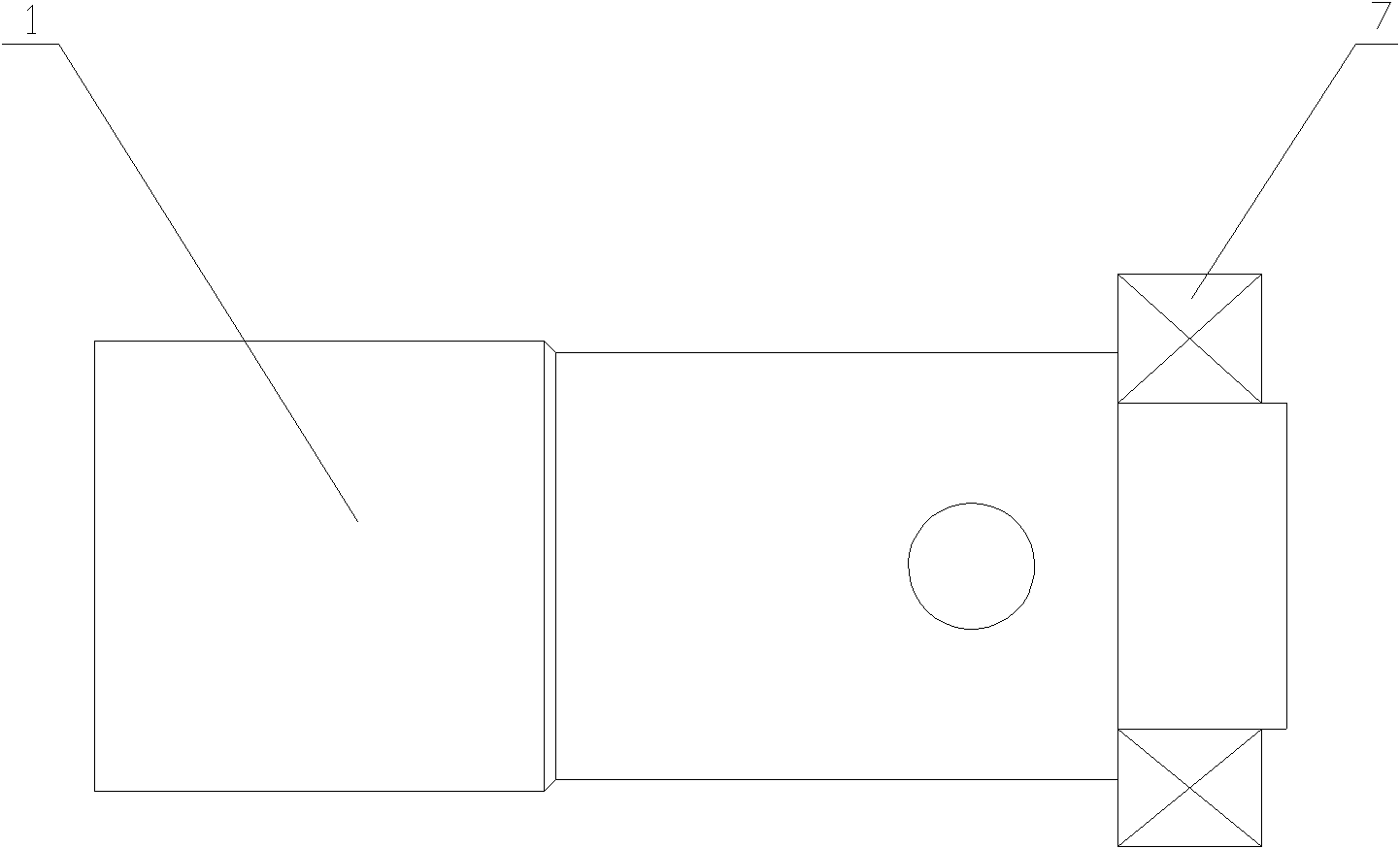
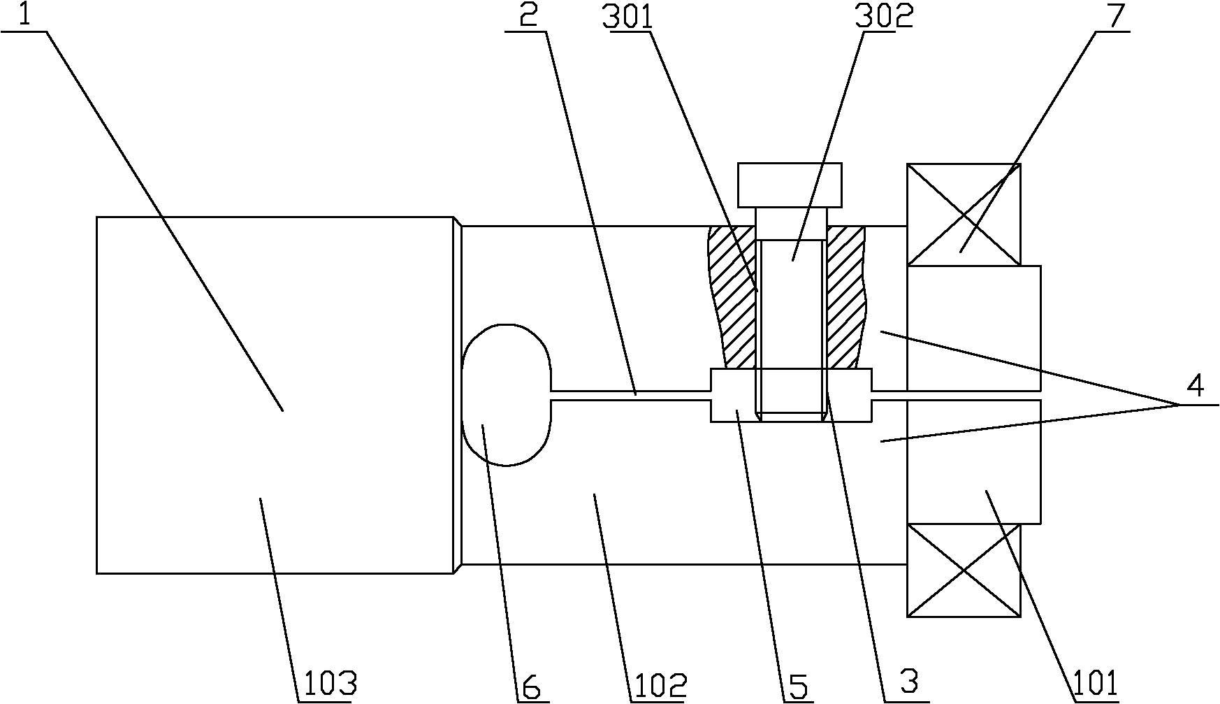
[0015] Such as figure 1 , figure 2 As shown, a tension transmission shaft includes a shaft body 1, one end of the shaft body 1 is cut along its axis direction with a 0.18mm molybdenum wire to form a gap 2, and the gap 2 can divide the end of the shaft body 1 into two forks The bifurcated part 4, the slit 2 passes through the shaft center, and the bifurcated part 4 is provided with an expansion device 3 for expanding it to fit with the fitting.

[0016] The expansion device 3 includes a threaded hole 301 which is arranged on one of the forks of the bifurcation part 4 and communicates with the seam 2. The screw 302 is installed in the threaded hole 301, and the bifurcation part 4 can be rotated by rotating the screw 302. Expand, so that the shaft body 1 and the fitting 7 are closely matched.

[0017] The shaft body 1 is a stepped shaft, including a first-level shaft 101 , a second-level shaft 102 and a third-level shaft 103 . The steps of the shaft can position the fitting 7 ...


PUM


Abstract

The invention discloses a tensioning transmission shaft which comprises a shaft body and is technically characterized in that one end of the shaft body is provided with a gap extending along the axes direction for segmenting the end part of the shaft body into forked forking parts, the gap passes through the axle center, and the forking parts are provided with a tensioning device which is expanded for being in tensioning and matching with a matching member. The tensioning device comprises a threaded hole communicated with the gap and arranged on one fork of the forking parts, and a bolt penetrates through the threaded hole; the shaft is also provided with a rectangular hole being communicated with the threaded hole and extending along the radial direction of the shaft; and an elliptical hole for eliminating stress is arranged at the tail part of the gap. The invention has an improved transmission force for ensuring coaxiality of a transmission member, and is suitable for thin products with higher coaxiality requirement.

Description

【Technical field】 [0001] The invention relates to a shaft transmission part, in particular to an expansion transmission shaft. 【Background technique】 [0002] In the process of mechanical transmission, it is necessary to ensure a high degree of coaxiality between the transmission parts. Commonly used parts are shafts, bearings and gears. In the assembly of shafts and bearings, shafts and gears, etc., keys or pins are usually used to connect. With such a connection, the torque is transmitted only by the contact surface of the key or the pin, and the transmission force is limited. When installing, it needs to be installed with a larger interference fit, that is, it needs to use a larger assembly force; when disassembling, it needs to use a larger knocking force, which is inconvenient to disassemble. Especially in small products with high coaxiality requirements, when using keys or pins to ensure product strength, the transmission torque will be greatly reduced, reducing the...

Claims


Application Information

Patent Timeline
Patent Type & Authority Applications(China)
IPC IPC(8): F16D1/08
Inventor 黄志强
Owner ZHONGSHAN JONJEE PRECISION MACHINERY
Learn More