


Quick Research
Generate reliable direction feasibility study reports for your R&D in just a few steps.

Technical Q&A
Discover and master advanced knowledge NOW. Basics, ideas, possibilities, all at once.

Find Solutions
As an expert in R&D theories, this can generate solutions to your technical problems instantly.

Evaluate Feasibility
Analyze your overall solution with one click, know your potential R&D risks in advance.

Monitor Landscape
Get weekly tech updates, stay abreast of the latest tech innovations and key insights.
Method of determining the conditions of a phase for machining a workpiece with modulated cutting rate
A technology for adjusting the cutting speed and cutting speed. It is used in the attachment of tool holders, metal processing equipment, manufacturing tools, etc., and can solve problems such as time loss and workpiece waste.
- Summary
- Abstract
- Description
- Claims
- Application Information
AI Technical Summary
Problems solved by technology
Method used
Image


Examples
Embodiment Construction
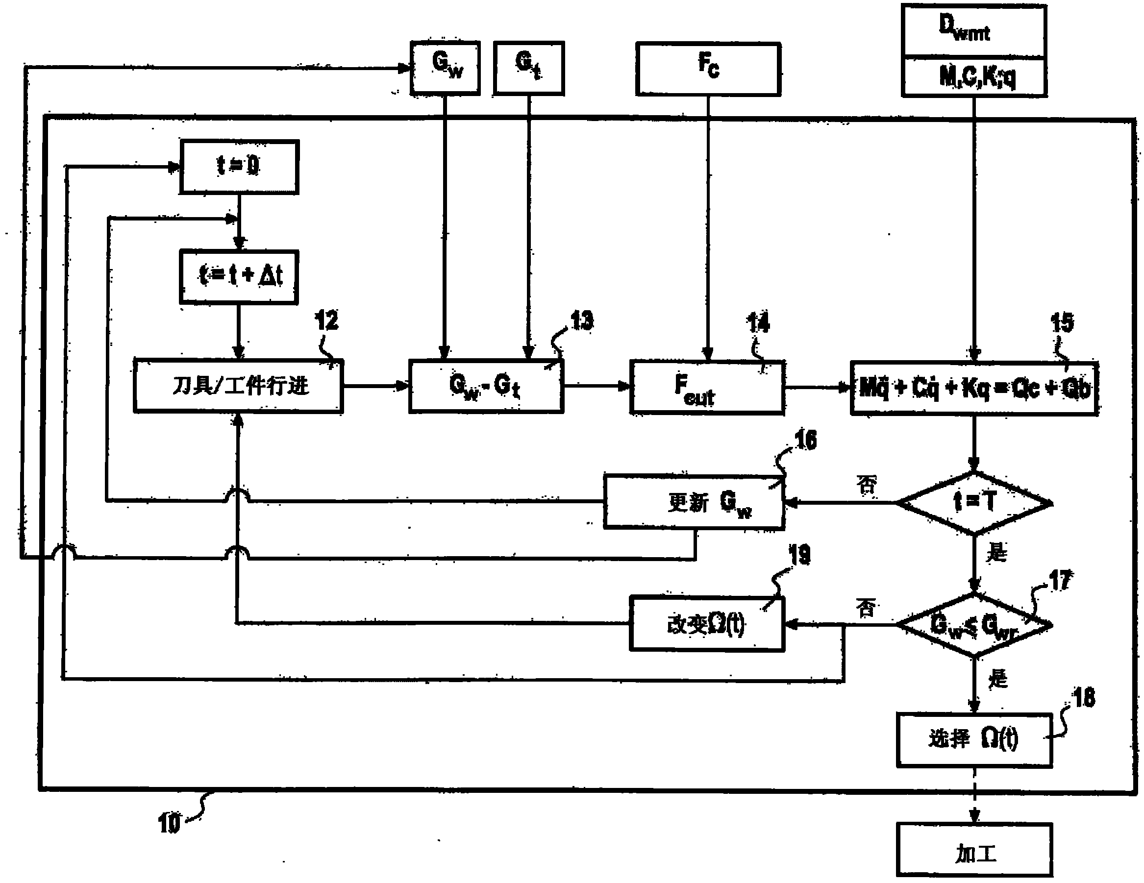
[0008] The attached figure depicts the simulated machining process. Assume that a machining operation is performed within a predetermined time T. Assume that T is a time interval within the predetermined time T. The smaller the value chosen for T, the more calculations need to be performed, but this allows an accurate description of the phenomenon and the shape of the part, including the state of the surface at the end of a machining operation. The machining operation is a machining phase in which the tool is continuously held in engagement with the material of the workpiece.
[0009] In addition, a variety of models can be used to represent the artifacts and components that make up the system in computer form, and to describe the interactions of the various artifacts and components with each other. Most models describing the mechanical behavior of workpieces and assemblies are made using the so-called "finite element" method. Artifacts or components are represented by grou...
PUM
 Abstract
Description
Claims
Application Information
 - R&D Engineer
- R&D Manager
- IP Professional
- Industry Leading Data Capabilities
- Powerful AI technology
- Patent DNA Extraction
Browse by: Latest US Patents, China's latest patents, Technical Efficacy Thesaurus, Application Domain, Technology Topic, Popular Technical Reports.
© 2024 PatSnap. All rights reserved.Legal|Privacy policy|Modern Slavery Act Transparency Statement|Sitemap|About US| Contact US: help@patsnap.com