
Fuel lid opening/closing device

A technology of opening and closing device and fuel tank cover, which is applied in the directions of power plant, transportation and packaging, and arrangement in combination with the fuel supply of internal combustion engines, etc., can solve the problem of difficulty in judging the degree of retraction and separation of stop pins.

Active Publication Date: 2011-07-27
PIOLAX CO LTD
View PDF1 Cites 5 Cited by
  • Summary
  • Abstract
  • Description
  • Claims
  • Application Information

AI Technical Summary

Problems solved by technology

However, it is difficult for the operator to judge the extent to which the stop pin is retracted according to the pulling of the cable by operating the handle.
So, the cable may be pulled more than necessary and may separate the end of the torsion spring from the head of the stop pin

Method used


Image

  • Fuel lid opening/closing device
  • Fuel lid opening/closing device
  • Fuel lid opening/closing device

Examples


Embodiment Construction

[0049] Hereinafter, embodiments of the present invention will be described in detail with reference to the drawings.

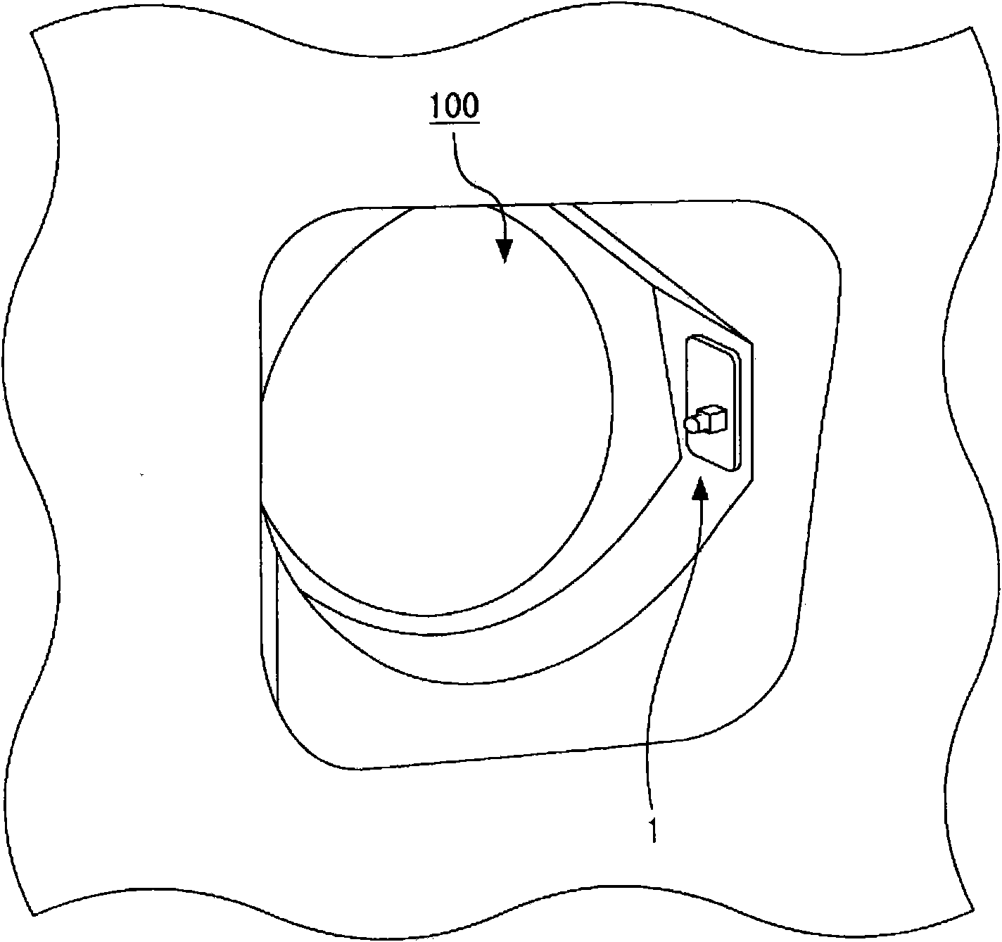
[0050] figure 1 is an enlarged perspective view showing a fuel filler port installed with the fuel cap opening and closing device according to the embodiment.

[0051] Generally speaking, the refueling recessed chamber 100 is arranged on the left or right side of the vehicle body, and a refueling port (not shown) is opened in the recessed chamber 100 . The opening in the recessed chamber 100 is designed to be opened and closed by a cover (not shown). The fuel cap opening and closing device 1 according to the present embodiment is fitted in a mounting hole (not shown) formed in the inner surface of the recessed chamber 100 from the outside.

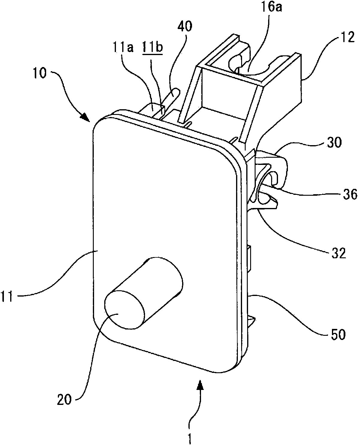
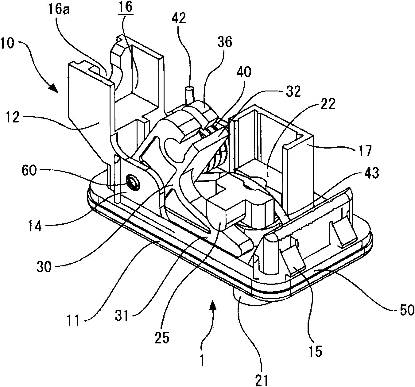
[0052] The fuel cap opening and closing device 1 includes a rod 20 that is telescopic in the axial direction. In a state where the rod is protruded into the recessed chamber 100, this rod 20 is engaged with an engaging...


PUM


Abstract

A link member (30) having a distal end side arm (31) extending in one direction and a proximal end side arm (32) extending in the other direction, and a rod (20) are built in the main body (10). The distal end side arm (31) of the link member (30) is narrower than the proximal end side arm (32) and formed by being shifted to the side opposite to the rod (20) built in at the adjacent position. Therod (20) is arranged to expose the distal end from the central part in the width direction of the surface of the main body (10).

Description

technical field [0001] The present invention relates to a fuel tank cover opening and closing device for opening and closing a cover for a fuel filler compartment provided in a vehicle body. Background technique [0002] For example, as prior art, Patent Document 1 discloses a configuration of such a fuel cap opening and closing device. In the device disclosed in the same document, a link is rotatably mounted to a housing, and a cable is locked to one end of the link while the other end of the link is engaged with a stopper pin. [0003] In the device thus constructed in Patent Document 1, the link is rotated in accordance with the pulling operation of the cable to retract the stopper pin into the inside of the housing. [0004] Here, as in Patent Document 1 image 3 As shown in , in the device of the same document 1, a stopper pin is arranged on the front side of the device at a position closer to one side edge than the center in the width direction. [0005] In general, ...

Claims


Application Information

Patent Timeline
IPC IPC(8): B60K15/05E05B65/12E05B79/08E05B79/20E05B79/22E05B83/34E05B85/22
CPCE05B83/34B60K15/05
Inventor 服部龙
Owner PIOLAX CO LTD
Learn More