Tilted fiber grating display screen realized by using optical fiber
A technology of fiber grating and display screen, applied in the direction of cladding fiber, optical waveguide light guide, instruments, etc., can solve the problems of low resolution, low brightness, and high display cost, and achieve resolution improvement, brightness assurance, and cost reduction. Effect
- Summary
- Abstract
- Description
- Claims
- Application Information
AI Technical Summary
Problems solved by technology
Method used
Image
Examples
Embodiment approach 1
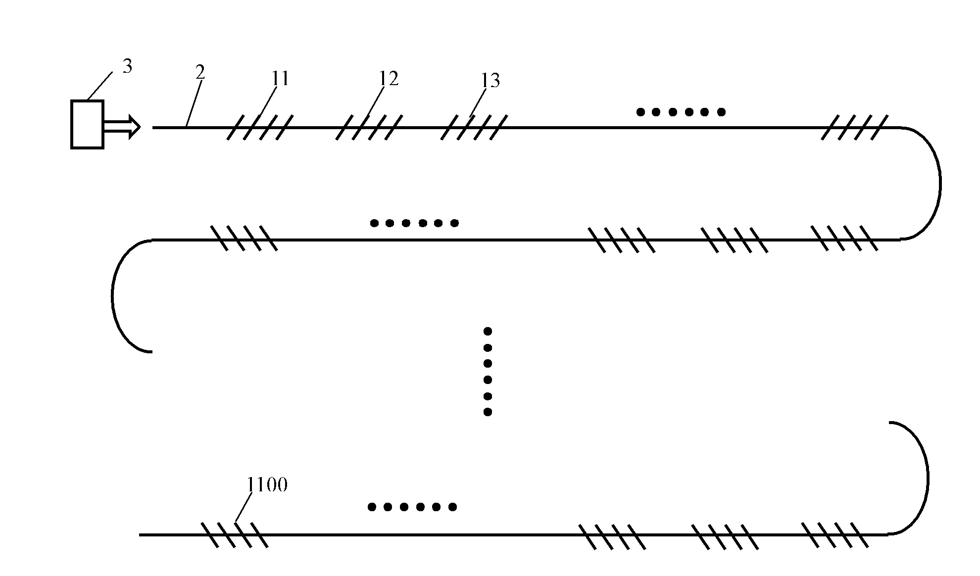
[0022] The oblique fiber grating display screen realized by optical fiber includes a laser 3, a multimode fiber 2, the first to Nth oblique fiber gratings 11, 12, 13, ..., 1N, and the light of the laser 3 engraved on the multimode fiber 2. The signal is input from multimode fiber 2, such as figure 1 shown.
[0023] Compared with ordinary fiber gratings, the angle between the angle between the refractive index distribution of the inclined fiber grating and the fiber is greater than 0° and less than 90°.
[0024] N is the number of pixels of the display screen, N=100~300000000 integer, arranged in an array of 10~30000*10~10000;
[0025] The laser 3 is a laser that outputs N wavelengths, and the N wavelengths output by the laser 3 correspond to the center wavelengths of the first to N slanted fiber gratings 11 , 12 , 13 , . . . , 1N.
[0026] The outer radius of the cladding of the multimode optical fiber 2 is 60-500 microns, and the radius of the core is 5-300 microns;
[002...
Embodiment approach 2
[0031] The oblique fiber grating display screen realized by optical fiber includes a laser 3, a multimode fiber 2, the first to hundredth oblique fiber gratings 11, 12, 13, ..., 1100, and laser 3 engraved on the multimode fiber 2. The optical signal is input from the multimode fiber 2, such as figure 2 shown.
[0032] The laser 3 is a laser that outputs one hundred wavelengths, and the one hundred wavelengths output by the laser 3 correspond to the center wavelengths of the first to the hundredth slanted fiber gratings 11 , 12 , 13 , . . . , 1100 one by one.
[0033] The outer radius of the cladding of the multimode fiber 2 is 60 microns, and the radius of the core is 5 microns.
[0034] The output wavelength range of the laser 3 is 390-394.95 nm; the interval between adjacent wavelengths is 0.05 nm.
[0035] The bandwidths of the first to the hundredth slanted fiber gratings 11, 12, 13, ..., 1100 are all 0.05nm, and the central wavelength is 390-394.95nm. The wavelength o...
Embodiment approach 3
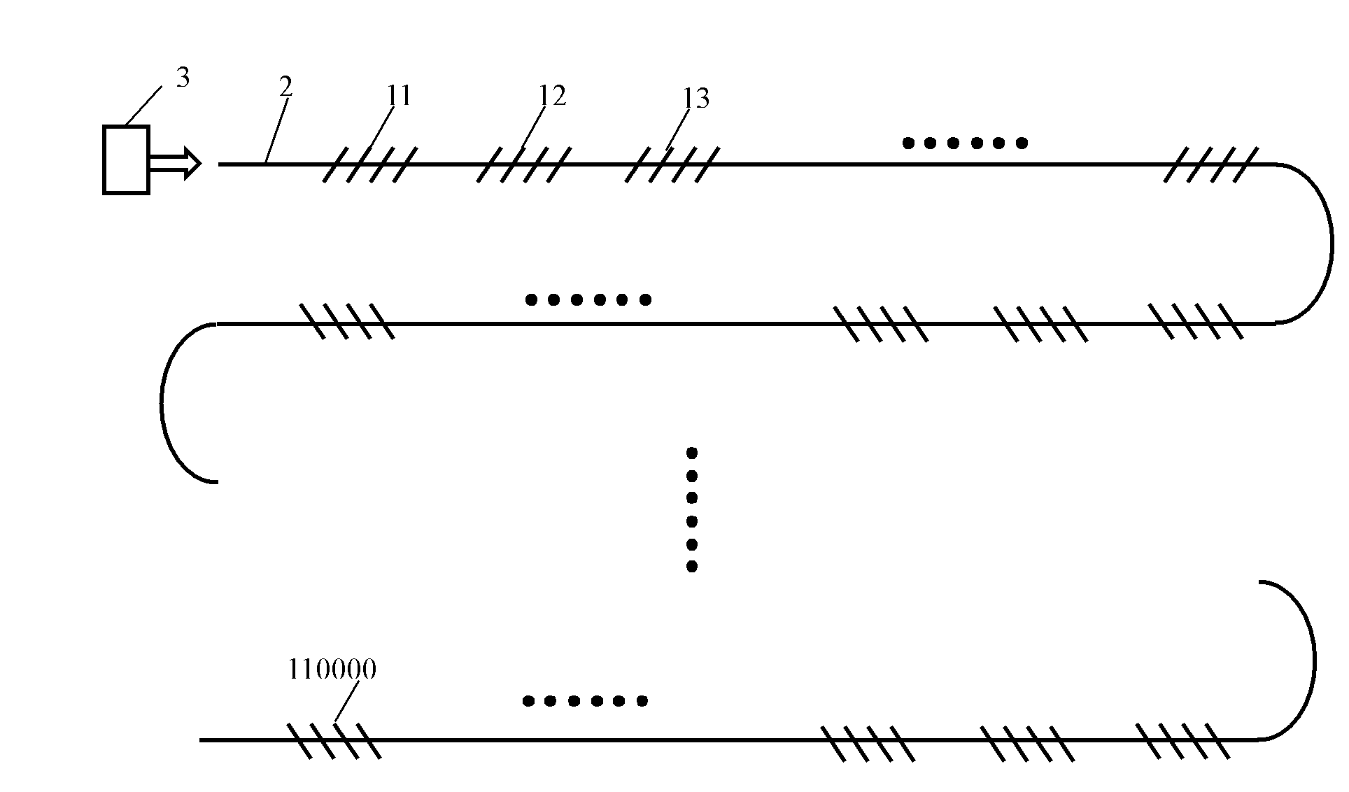
[0039] The oblique fiber grating display screen realized by optical fiber includes a laser 3, a multimode fiber 2, the first to the first ten thousand oblique fiber gratings 11, 12, 13, ..., 110000, laser 3 carved on the multimode fiber 2 The optical signal is input from the multimode fiber 2, such as image 3 shown.
[0040] The laser 3 is a laser that outputs 10,000 wavelengths, and the 10,000 wavelengths output by the laser 3 correspond to the central wavelengths of the first to the first 10,000-slope fiber gratings 11, 12, 13, . . . , 110,000.
[0041] The outer radius of the cladding of the multimode fiber 2 is 100 microns, and the radius of the core is 10 microns.
[0042] The output wavelength range of the laser 3 is 720.005-770nm; the interval between adjacent wavelengths is 0.005nm.
[0043] The bandwidth of the first to the first 10,000-slope fiber gratings 11, 12, 13, ..., 110,000 are all 0.005nm, and the central wavelength range is 720.005-770nm. The wavelength ...
PUM
 Abstract
Description
Claims
Application Information
 - R&D
- Intellectual Property
- Life Sciences
- Materials
- Tech Scout
- Unparalleled Data Quality
- Higher Quality Content
- 60% Fewer Hallucinations
Browse by: Latest US Patents, China's latest patents, Technical Efficacy Thesaurus, Application Domain, Technology Topic, Popular Technical Reports.
© 2025 PatSnap. All rights reserved.Legal|Privacy policy|Modern Slavery Act Transparency Statement|Sitemap|About US| Contact US: help@patsnap.com


