
Mechanical swivel joint seal device

A technology of rotary joints and sealing devices, which is applied to the sealing of engines, mechanical equipment, engine components, etc., can solve problems such as easy vibration and noise, speed limitation, and gaps in coordination, and achieve simple and easy technical means and increase operating speed , the effect of small dynamic interference

Inactive Publication Date: 2011-07-20
SOUTH CHINA UNIV OF TECH
View PDF7 Cites 11 Cited by
  • Summary
  • Abstract
  • Description
  • Claims
  • Application Information

AI Technical Summary

Problems solved by technology

[0005] (1) The structure is complex and the number of components is large, resulting in an increase in cost
[0006] (2) The volume is large, which affects the performance of some equipment using mechanical seals
[0007] (3) The rotational speed is limited. In addition to the limitation of the friction and wear properties of the material, high-speed vibration is also a reason. There are many components and there are gaps between them. High-speed rotation is prone to vibration and noise.

Method used


Image

  • Mechanical swivel joint seal device
  • Mechanical swivel joint seal device
  • Mechanical swivel joint seal device

Examples


Embodiment

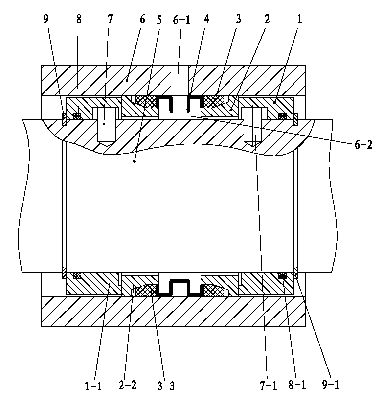
[0031] Such as figure 1 As shown, the mechanical rotary joint sealing device of the present invention is embedded between the shaft 5 and the housing 6 and seals the fluid between the housing 6 and the shaft 5. It has two moving rings 1, 1-1, Two static rings 2, 2-2, two rubber rings 3, 3-3, and a spacer sleeve 4; the moving rings 1, 1-1 are respectively located at the outermost ends of the shaft 5 and are sealed and fixedly connected with the shaft 5; The static rings 2, 2-2 are respectively located inside the moving rings 1, 1-1, and their outer end faces contact the inner end faces of the moving rings 1, 1-1 to form a sealing friction pair; the rubber rings 3, 3-3 are respectively sleeved On the static ring 2, 2-2, its outer circle fits with the inner circle of the shell 6, and the inner circle of the rubber ring 3, 3-3 is matched with the outer cone of the static ring 2, 2-2; the elastic spacer 4 is located In the sealed cavity 6-2 formed between the rubber rings 3 and 3-3,...


PUM


Abstract

The invention discloses a mechanical swivel joint seal device which comprises two moving rings, two stationery rings, two rubber gaskets and a spacer sleeve, wherein the moving rings are arranged at the outermost side, sealed with a shaft and fixedly connected with the shaft; the stationery rings are arranged at the inner sides of the moving rings and form seal friction pairs with the moving rings; the rubber gaskets are sleeved between the stationery rings and a shell, and inner circles of the rubber gaskets are in a 20 DEG taper fitting with outer circles of the stationery rings; the spacer sleeve is arranged between the two rubber gaskets, the cross section of the spacer sleeve is in the shape of a spring curve, the spacer sleeve has elasticity in the axial direction, and the outer diameter of the spacer sleeve is 0.1-0.2mm bigger than the inner diameter of the shell; an opening which is 2-3mm wide is arranged on the circumference of the spacer sleeve, so that the spacer sleeve keeps certain expansion force and is pressed against the shell after being sleeved in the shell; the end surface of the spacer sleeve is in contact with the inner end surfaces of the rubber gaskets, and the stationery rings are supported on an inner circle of the shell through the taper quioning action of the rubber gaskets under the elasticity action of the spacer sleeve and the pressure action of a seal medium. The mechanical swivel joint seal device has a simple structure, a small volume and a vibration damping effect due to the support of the rubber gaskets, stably runs and is suitable for high-speed running.

Description

Technical field [0001] The invention relates to the field of mechanical seals, in particular to a mechanical rotary joint sealing device. Background technique [0002] High-speed and high-pressure mechanical rotary joints usually use mechanical sealing devices. Two friction pairs are used on both sides of the sealed cavity. The friction pairs are made of hard metal and other wear-resistant and high-temperature materials. The mechanical seal of hard materials is generally composed of a static ring (fixed with the housing), a moving ring (fixed with the shaft), a spring and other elements. Because the shaft and the moving ring have radial runout during operation, it is difficult to adopt the radial sealing method. Therefore, the mechanical seals on the market are mainly end face seals, that is, the end faces of the moving ring and the static ring are in the fluid pressure and compensation elastic force (spring Under the action of force), it can keep close and make relative sliding...

Claims


Application Information

Patent Timeline
Patent Type & Authority Applications(China)
IPC IPC(8): F16J15/18F16J15/34F16J15/46
Inventor 迟永滨
Owner SOUTH CHINA UNIV OF TECH
Learn More