Cutting device

A technology of cutting device and cutting table, which is applied in metal processing and other directions, and can solve problems such as inability to cut

Active Publication Date: 2011-07-20
SHIMA SEIKI MFG LTD
View PDF7 Cites 8 Cited by
  • Summary
  • Abstract
  • Description
  • Claims
  • Application Information

AI Technical Summary

Problems solved by technology

The inventors proposed the present invention by paying attention to the following problem: If the material to be cut becomes thick due to stacking, etc., the projected cutting pattern is different from the actual cutting pattern, and therefore, cutting cannot be performed as confirmed by the operator

Method used


Image

  • Cutting device
  • Cutting device
  • Cutting device

Examples


Embodiment Construction

[0050] The best examples for carrying out the invention are shown below. The scope of the present invention should be interpreted in consideration of the possibility of changes based on known techniques in the description of claims.

[0051] 【Example】

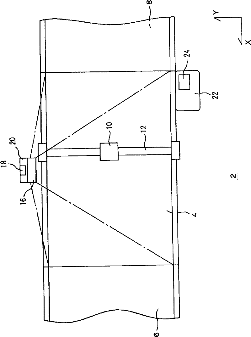
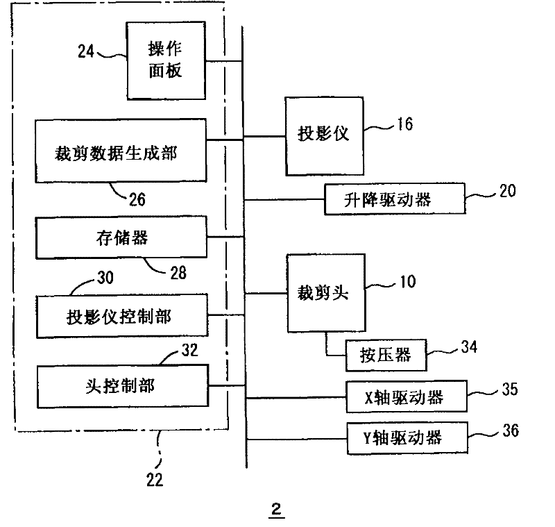
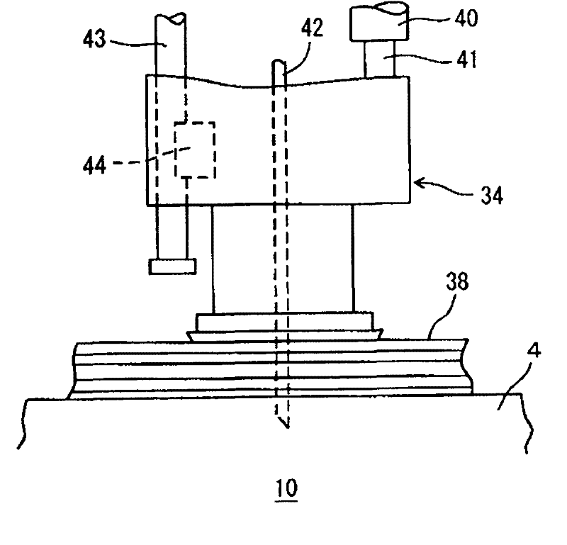
[0052] Figure 1 to Figure 4 Represent the cutting device 2 of embodiment among, Figure 5 , Figure 6 A cutting device 3 of a modified example is shown in . In each figure, 4 is a cutting table, and a pick-up table 6 is provided on the downstream side thereof, and a clothing material transfer table 8 is provided on the upstream side, and the material to be cut is moved between them by a conveyor not shown. In addition, among the materials to be cut, the thickness of each piece of leather, or a plurality of laminated fabrics, etc., is less than 1 cm when it is thin, and about several cm when it is thick. Also there are thicker leathers and thinner leathers in leather. In addition, the pick-up table 6 and the clothing mate...


PUM


Abstract

The present invention provides a cutting device which comprises a cutting platform, a cutting head, and a projector which projects an image that represents cutting information on the cutting platform. A thickness of the measured material is measured, and the dimension of the projected image is corrected according to a measured thickness. Furthermore the dimension of the image that is projected by the projector is instant irrelatively with the thickness of the cut material. Even when the thickness of the cut material is changed, the cutting can be performed similarly with the projection of the projector.

Description

technical field [0001] The present invention relates to a cutting device for projecting an image representing cutting information on a material to be cut. Background technique [0002] Japanese Patent Application Laid-Open No. 07-324213 (Patent Document 1) discloses a technique of projecting a cutting pattern on a material to be cut, such as leather, from a projection device such as a projector. Here, if the cutting pattern has problems such as contact with flaws in the leather or mismatching with the pattern of the cloth as the material to be cut, the operator moves the cutting pattern so that it matches the material to be cut and positions the cutting pattern. [0003] In order to improve production efficiency, materials to be cut such as cloth are layered and cut. The inventors proposed the present invention focusing on the problem that if the material to be cut becomes thick due to lamination or the like, the projected cutting pattern is different from the actual cuttin...

Claims


Application Information

Patent Timeline
Patent Type & Authority Applications(China)
IPC IPC(8): B26D5/00
Inventor 有北礼治
Owner SHIMA SEIKI MFG LTD
Why Eureka
Try Eureka