Vacuum air pumping device

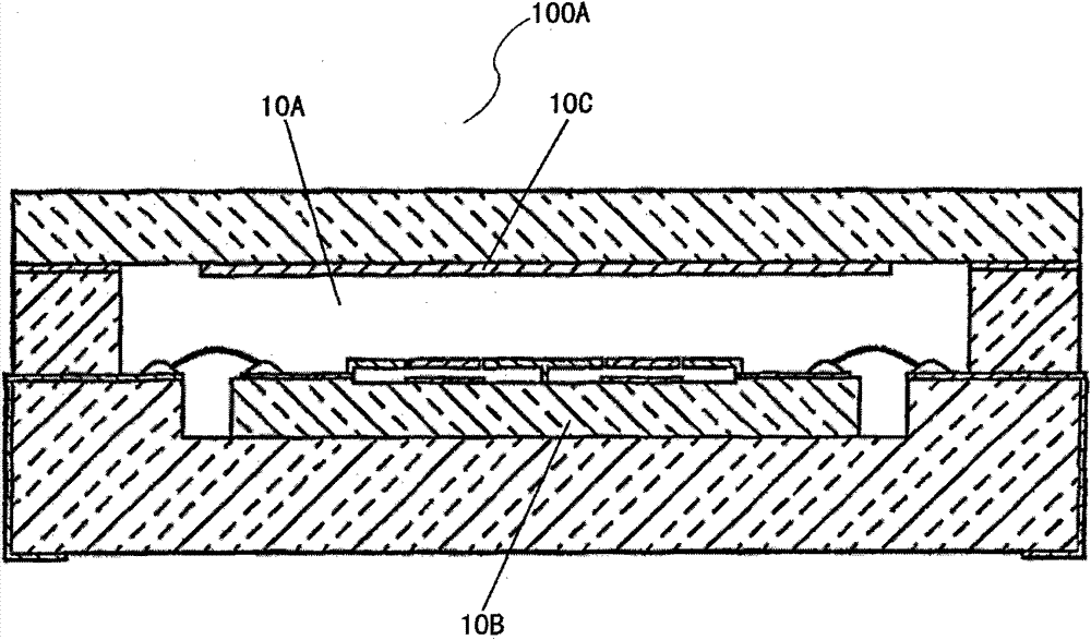
The technology of a vacuum pumping device and a vacuum pump, which is applied in the direction of obtaining/maintaining vacuum, can solve the problems of damage to the electric vacuum device 10B, and achieve the effects of easy replacement, simple structure, and small appearance

Active Publication Date: 2013-01-30
INST OF PHYSICS - CHINESE ACAD OF SCI
View PDF1 Cites 0 Cited by
  • Summary
  • Abstract
  • Description
  • Claims
  • Application Information

AI Technical Summary

Problems solved by technology

For example, the micro-device assembly disclosed in the Chinese invention patent with the patent number "ZL200480007790.0" and the name "micro-device assembly with a fine-grained getter layer for maintaining vacuum", such as figure 1 as shown, figure 1 It is a schematic structural diagram of a vacuum chamber with a getter in the prior art. It can be seen from the figure that both the getter 10C and the electric vacuum device 10B are arranged in the vacuum chamber 10A, and when the getter 10C in the vacuum chamber 10A is activated, it is necessary to The entire microdevice assembly 100A is heated, which may cause damage to the electric vacuum device 10B when the getter 10C is activated at high temperature

Method used


Image

  • Vacuum air pumping device
  • Vacuum air pumping device
  • Vacuum air pumping device

Examples


Embodiment Construction

[0056] Below in conjunction with accompanying drawing, structural principle and working principle of the present invention are specifically described:

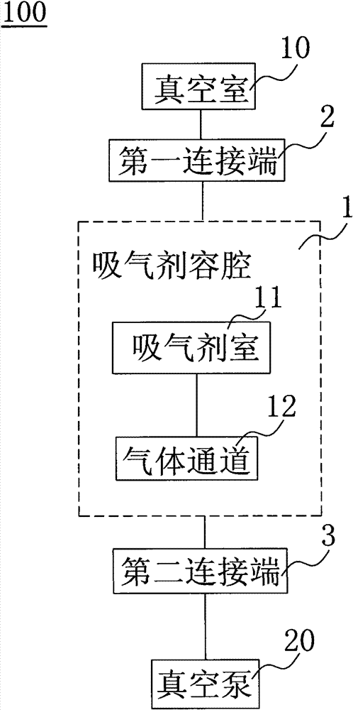
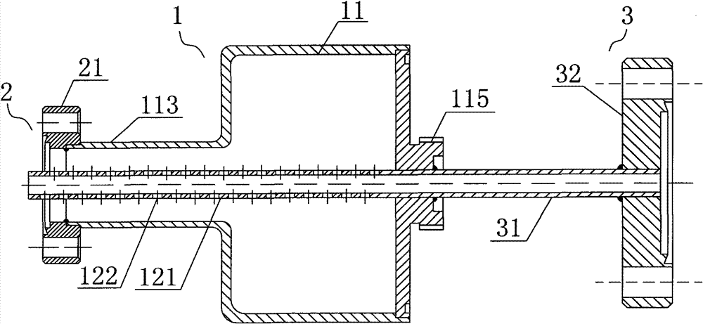
[0057] see figure 2 , figure 2 It is a structural block diagram of the present invention. The vacuum pumping device 100 of the present invention includes a vacuum chamber 10, a vacuum pump 20 and a getter 30, the getter 30 is used for high-temperature heating activation to obtain and maintain the vacuum degree of the container, and the getter 30 is accommodated The container is a getter chamber 1 independently arranged between the vacuum chamber 10 and the vacuum pump 20, and the getter chamber 1 communicates with the vacuum chamber 10 and the vacuum pump 20 respectively. The getter chamber 1 can be heated separately to achieve high temperature activation of the getter 30 without causing thermal damage to the devices in the vacuum chamber 10 .

[0058] Wherein, the getter chamber 1 is respectively connected to the vacuum ...


PUM


Abstract

A vacuum air pumping device comprises a vacuum chamber, a vacuum pump and a getter, wherein the getter is used for heating at high temperature and activating so as to obtain and maintain the vacuum degree of a container; the container for accommodating the getter is a getter accommodation chamber which is independently arranged between the vacuum chamber and the vacuum pump; and the getter accommodation chamber is respectively communicated with the vacuum chamber and the vacuum pump. When the vacuum air pumping device is in use, only part of the getter is heated and the vacuum chamber and devices inside the vacuum chamber are not heated; and the vacuum air pumping device has the advantages of favorable sealing effect, convenience in mounting, use and replacement, small size, and simple structure..

Description

technical field [0001] The invention relates to a suction device, in particular to a vacuum suction device with a high-temperature activated getter. Background technique [0002] Getters play a very important role in electric vacuum devices, vacuum technology, atomic energy industry and other scientific research and production. Especially in the electric vacuum device, it can not only make the device obtain the required vacuum degree, but also make the device maintain a certain vacuum degree, so as to ensure the stability and reliability of the electric vacuum device. The commonly used structure for placing the getter is that the getter and the device are placed together in a vacuum chamber that needs to maintain a vacuum; when the getter is activated at high temperature, the entire vacuum chamber is baked at a high temperature. For example, the micro-device assembly disclosed in the Chinese invention patent with the patent number "ZL200480007790.0" and the name "micro-devi...

Claims


Application Information

Patent Timeline
Patent Type & Authority Patents(China)
IPC IPC(8): H01J19/70
Inventor 李国强边勇波黎红崔彬王佳郭进何晓锋李超李娜张强李春光张雪强何豫生
Owner INST OF PHYSICS - CHINESE ACAD OF SCI
Why Eureka
Try Eureka