Slide-type vehicle conveying system and slide-type vehicle conveying method

A conveying system and skid-type technology, applied in the direction of conveyors, conveyor objects, mechanical conveyors, etc., can solve the problems of low cost, high cost, and low conveying efficiency, so as to save space and cost, reduce transportation costs, The effect of improving installation efficiency

Active Publication Date: 2013-01-02
NUCTECH CO LTD
View PDF0 Cites 0 Cited by
  • Summary
  • Abstract
  • Description
  • Claims
  • Application Information

AI Technical Summary

Problems solved by technology

[0002] When the existing small passenger cars to be inspected need to be scanned and inspected, there are mainly three transportation methods: one is to use a large flat plate with its own driving device to reciprocate on the track to realize the transportation. This method mainly has a large area , high cost and other disadvantages; the other is to use a drag device with its own drive and a card wheel mechanism to reciprocate on the track to achieve transportation. This method still has the disadvantage of high cost, and this method has the card The drag device of the mechanism reciprocates on the track, which is intermittent work, and the transmission efficiency is low
At the same time, using this method, the small passenger car cannot pull the handbrake after parking, which is very different from our usual habit of parking the handbrake, which is likely to cause misoperation and safety accidents; the third method is to install push rollers on the chain and use the chain to reciprocate. This method of transporting small passenger cars has high efficiency and low cost, but there is still the disadvantage that the handbrake cannot be pulled after the small passenger car is parked, which may easily cause misoperation

Method used


Image

  • Slide-type vehicle conveying system and slide-type vehicle conveying method
  • Slide-type vehicle conveying system and slide-type vehicle conveying method
  • Slide-type vehicle conveying system and slide-type vehicle conveying method

Examples


Embodiment Construction

[0058] The technical solutions of the present invention will be further specifically described below through the embodiments and in conjunction with the accompanying drawings. In the specification, the same or similar reference numerals designate the same or similar components. The following description of the embodiments of the present invention with reference to the accompanying drawings is intended to explain the general inventive concept of the present invention, but should not be construed as a limitation of the present invention.

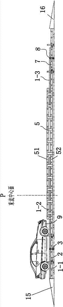
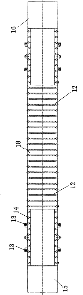
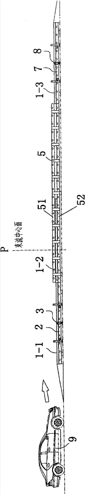
[0059] see figure 1 -3, which shows a skid-type vehicle conveying system, including: an entrance conveying platform 2, including: an entrance vertical lifting device 3, which is set to be able to move in the first horizontal position ( figure 1 horizontal position in ) and the second horizontal position ( Figure 3C vertically move between the horizontal position in the center); the conveying device 18 arranged on the upper end of the vertic...


PUM


Abstract

The invention discloses a slide-type vehicle conveying system, which comprises an inlet conveying platform, an outlet conveying platform and a middle conveying platform. An inlet vertical lifting device can vertically move between a first horizontal position and a second horizontal position. An outlet vertical lifting device can vertically move between the first horizontal position and the second horizontal position. The middle conveying platform is arranged between the inlet conveying platform and the outlet conveying platform and composed of upper and lower conveying layers. A conveying device comprises the inlet conveying platform, the outlet conveying platform, and a plurality of supporting rollers arranged at the upper ends of the upper and lower conveying layers of the middle conveying platform. Driving means are provided for the inlet conveying platform, the outlet conveying platform, and the upper and lower conveying layers of the middle conveying platform respectively and are used for driving the plurality of supporting rollers to move synchronously so as to convey a skid arranged on the plurality of supporting rollers. Via the technical scheme, the fast conveying of small-sized passenger cars is solved, and the safety checking of the small-sized passenger cars is realized.

Description

technical field [0001] The invention relates to a vehicle conveying system and a vehicle conveying method, which belong to the technical field of ray perspective scanning and conveying, are suitable for the occasion of fast conveying small passenger cars, and can also be used in the technical field of logistics conveying. Background technique [0002] When the existing small passenger cars to be inspected need to be scanned and inspected, there are mainly three transportation methods: one is to use a large flat plate with its own driving device to reciprocate on the track to realize the transportation. This method mainly has a large area , high cost and other disadvantages; the other is to use a drag device with its own drive and a card wheel mechanism to reciprocate on the track to achieve transportation. This method still has the disadvantage of high cost, and this method has the card The drag device of the mechanism reciprocates on the track, which is intermittent work, a...

Claims


Application Information

Patent Timeline
Patent Type & Authority Patents(China)
IPC IPC(8): B65G49/00B65G37/00B65G13/04B65G13/06G01N23/02
Inventor 何远胡斌齐祥安
Owner NUCTECH CO LTD
Why Eureka
Try Eureka