Antenna evaluation device and method
An antenna evaluation and antenna technology, which is applied to antennas, measuring devices, antenna radiation patterns, etc., and can solve problems such as inability to correct the phase of radio waves
- Summary
- Abstract
- Description
- Claims
- Application Information
AI Technical Summary
Problems solved by technology
Method used
Image

Examples
no. 1 Embodiment approach
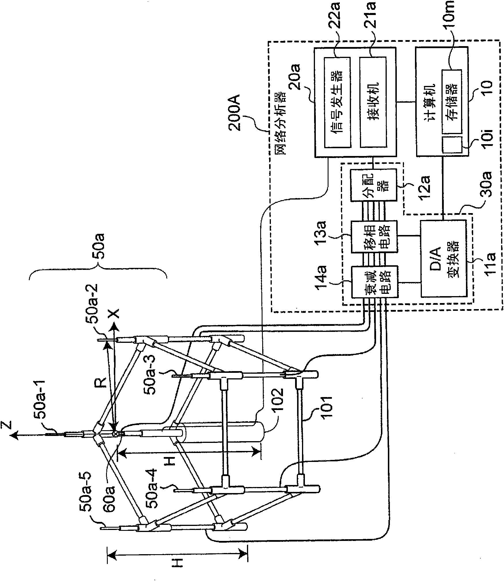
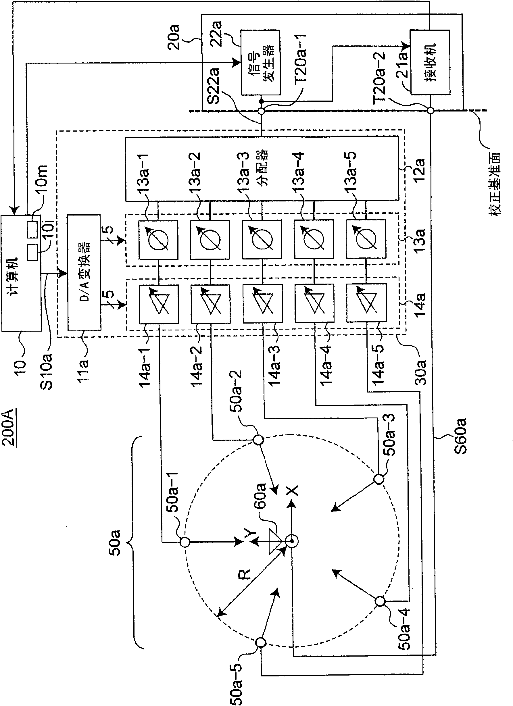
[0065] figure 1 It is a perspective view of main parts showing the configuration of an antenna evaluation device (also referred to as a spatially multiplexed wave generating device or a fading simulator) according to the first embodiment of the present invention, figure 2 yes means figure 1 A block diagram of the configuration of the multiplexed wave control measurement device 200A.
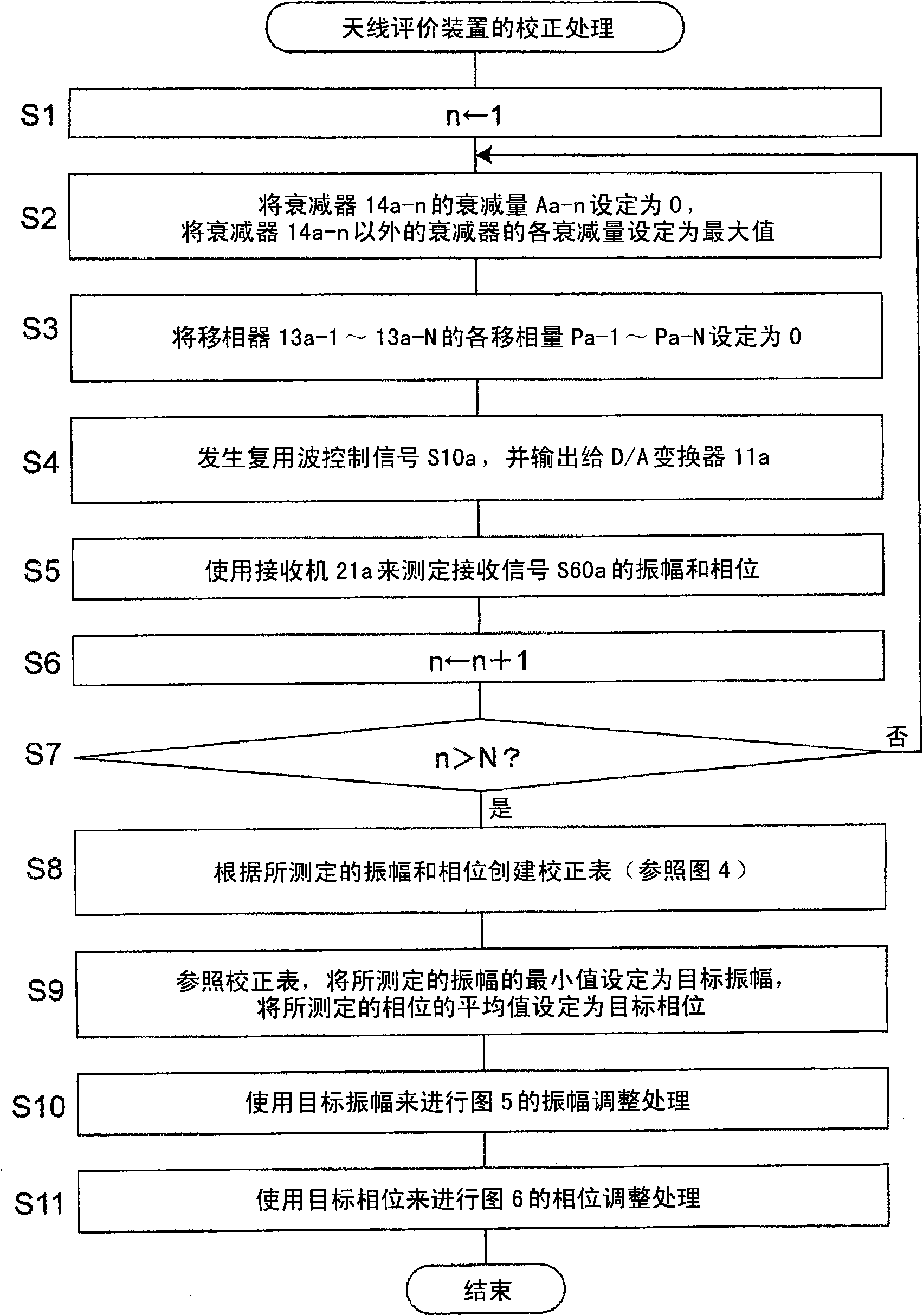
[0066] As will be described later in detail, the antenna evaluation device according to this embodiment is characterized in that the computer 10 controls the transmission circuit 30a such that the scatterer antennas 50a-n (n=1, 2, . . . , N, In the present embodiment, N is 5) radiate radio waves individually, and perform calibration as follows: The transmission circuit 30a is controlled based on the radio waves radiated independently from the scatterer antennas 50a-n so that the received signals respectively measured by the calibration receiving antennas 60a The amplitude of S60a coincides w...
no. 2 Embodiment approach
[0089] Figure 8 is a block diagram showing the configuration of a multiplex wave control measurement device 200B according to the second embodiment of the present invention, Figure 9 yes means Figure 8 A flowchart of the calibration process of the antenna evaluation device executed by the computer 10 of FIG. Compared with the multiplexed wave control generation device 200A according to the first embodiment, the multiplexed wave control measurement device 200B according to this embodiment is characterized by further comprising: a network analyzer 20b including a receiver 21b, a The amplitude phase adjustment circuit 72 and the attenuator 84 of the phase unit 73 and the attenuator 74 are performed using an array antenna including receiving antennas 60a and 60b arranged at a distance of half a wavelength from each other. Figure 9 correction processing.
[0090] Receiving antennas 60a and 60b are half-wavelength dipole antennas that receive vertically polarized radio waves,...
no. 3 Embodiment approach
[0102] Figure 10 It is a block diagram showing the configuration of a multiplex wave control measurement device 200C according to the third embodiment of the present invention. and, Figure 11 (a) means Figure 10 An explanatory diagram of the arrangement of the scatterer antennas 50a-1 to 50a-5 and the receiving antenna 60av at the time of the correction of the vertically polarized wave executed by the computer 10, Figure 11 (b) means Figure 10 An explanatory diagram of the arrangement of the scatterer antennas 50b-1 to 50b-5 and the receiving antenna 60ah when the computer 10 executes the correction of the horizontally polarized wave. Compared with the multiplexed wave control generation device 200A according to the first embodiment, the multiplexed wave control measurement device 200C according to this embodiment is characterized by further comprising: The pole antenna is the scatterer antenna group 50b of the scatterer antennas 50b-1 to 50b-5, the distributor 40, an...
PUM
 Abstract
Description
Claims
Application Information
 - R&D
- Intellectual Property
- Life Sciences
- Materials
- Tech Scout
- Unparalleled Data Quality
- Higher Quality Content
- 60% Fewer Hallucinations
Browse by: Latest US Patents, China's latest patents, Technical Efficacy Thesaurus, Application Domain, Technology Topic, Popular Technical Reports.
© 2025 PatSnap. All rights reserved.Legal|Privacy policy|Modern Slavery Act Transparency Statement|Sitemap|About US| Contact US: help@patsnap.com