
Rear tray mounting structure

A rear pallet and structure technology, which is applied in the field of rear pallet installation and structure, can solve problems such as poor operability and difficulty in grasping the positional relationship between interior parts and partitions, and achieve improved workability, improved aesthetics, and improved The effect of installation workability

Inactive Publication Date: 2011-06-22
HONDA MOTOR CO LTD
View PDF7 Cites 1 Cited by
  • Summary
  • Abstract
  • Description
  • Claims
  • Application Information

AI Technical Summary

Problems solved by technology

[0010] However, in the case of the prior art in which a partition is used for installing an interior trim, since the partition is disposed on the complete rear side of the interior trim, it is difficult to grasp the relationship between the interior trim and the interior trim when installing the interior trim. There is a problem of poor operability due to the positional relationship of the partition

Method used


Image

  • Rear tray mounting structure
  • Rear tray mounting structure
  • Rear tray mounting structure

Examples


Embodiment Construction

[0060] Hereinafter, preferred embodiments of the present invention will be described with reference to the drawings. In addition, in the following description, unless otherwise specified, the front-rear direction and the up-down direction refer to the front-rear and up-down directions with respect to the vehicle. In addition, in each embodiment, the same code|symbol is attached|subjected to the same part, and repeated description is abbreviate|omitted.

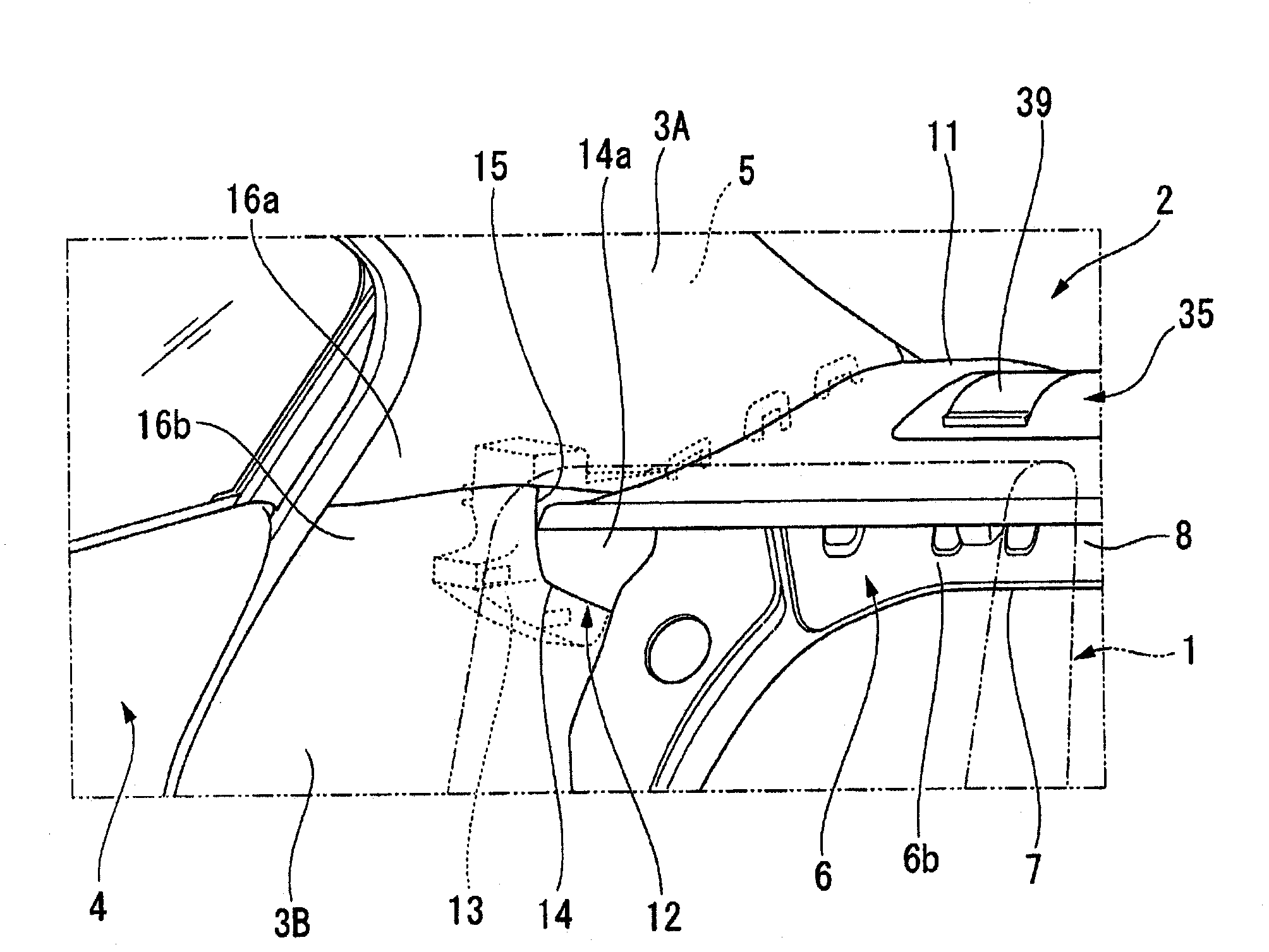
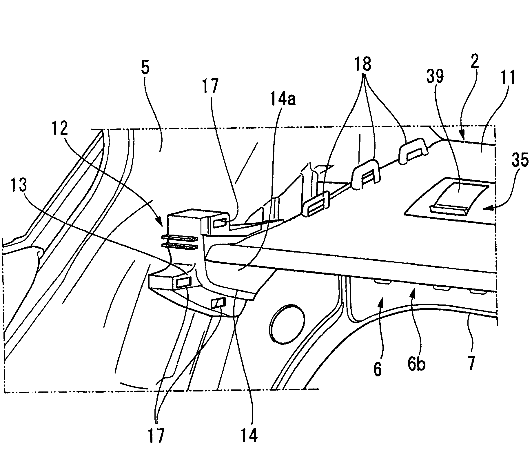
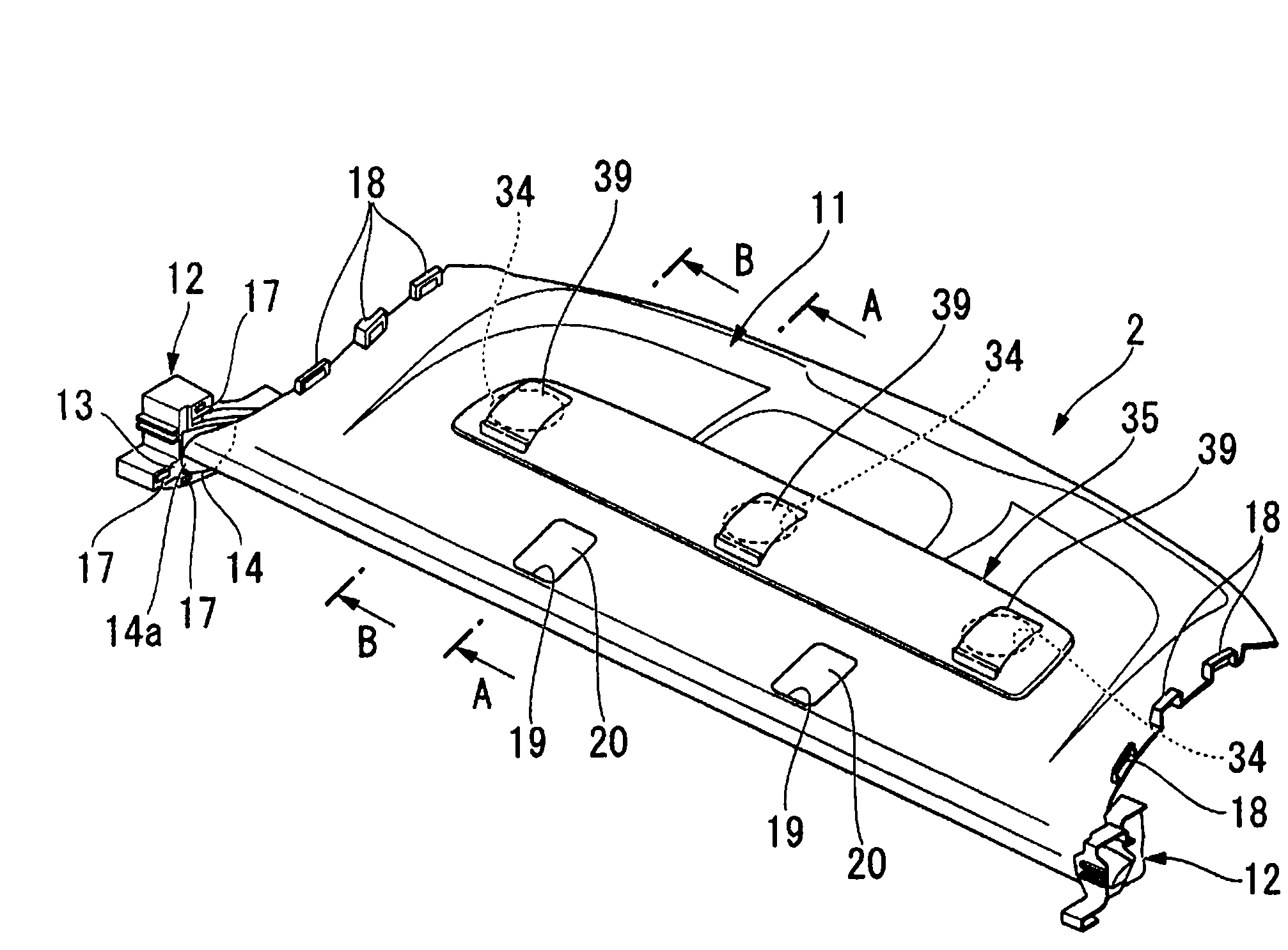
[0061] first of all, yes Figure 1 to Figure 7 A first embodiment of the present invention is shown and described.

[0062] figure 1 It is a perspective view looking at the rear part of the vehicle body of a sedan-type vehicle from the inside of a passenger compartment. Reference numeral 1 denotes a seat back of a rear seat. Reference numeral 2 denotes a rear tray (indoor component) arranged approximately horizontally on the rear side of the seat back 1 . Reference numerals 3A and 3B denote resin interior trims that are a...


PUM


Abstract

A rear tray mounting structure, wherein a rear tray is mounted to a vehicle body so as to cover a gap between a seatback and a vehicle body-side support member behind the seatback. A rear tray mounting section for mounting the rear tray thereon is provided to that surface of the vehicle body-side support member which faces the gap.

Description

technical field [0001] The present invention relates to an attachment structure of a rear tray arranged behind a rear seat of a vehicle. [0002] This application is based on Japanese Patent Application No. 2008-226112 filed in Japan on September 3, 2008, Japanese Patent Application No. 2008-226113 filed in Japan on September 3, 2008, and Japanese Patent Application No. 2008-226113 filed in Japan on September 3, 2008 Priority is claimed based on Japanese Patent Application No. 2008-226114, and its contents are incorporated herein. Background technique [0003] In a sedan-type vehicle or the like, a rear tray is arranged on the rear side of the seat backs of the rear seats (for example, refer to Patent Document 1). Usually, the rear tray is attached to the vehicle body by screwing the left and right side edges of the rear tray to members on the vehicle body side, or the like. [0004] However, in such a mounting structure of the rear tray, the mounting work is difficult bec...

Claims


Application Information

Patent Timeline
Patent Type & Authority Applications(China)
IPC IPC(8): B60R7/08
CPCB60R5/044
Inventor 谷俊彦小村辉基清野祝
Owner HONDA MOTOR CO LTD
Learn More