Travelling-wave linear ultrasonic micromotor
An ultrasonic and traveling-wave technology, applied in the field of traveling-wave linear ultrasonic micro-motors, can solve problems such as difficult adjustments and drastic changes in motor performance, and achieve the effects of compact structure, improved working stability and precision, and broad application prospects
Active Publication Date: 2011-06-15
GUANGDONG JIAHE MICROMOTOR
View PDF4 Cites 24 Cited by
- Summary
- Abstract
- Description
- Claims
- Application Information
AI Technical Summary
Problems solved by technology
Since different types of vibration modes have different sensitivities to changes in external conditions, when conditions such as temperature, pre-pressure, and drive signal voltage change, it is easy to affect the composite vibration of the stator using different types of composite vibration modal motors, making the motor Performance varies wildly and is not easily tuned
Method used
View moreImage
Smart ImageViewing Examples
Examples
Embodiment 1
Embodiment 2
Embodiment 3
Login to View More PUM
 Abstract
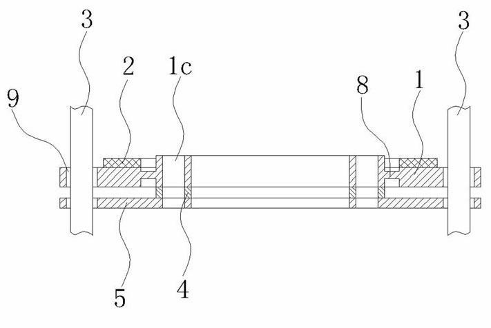
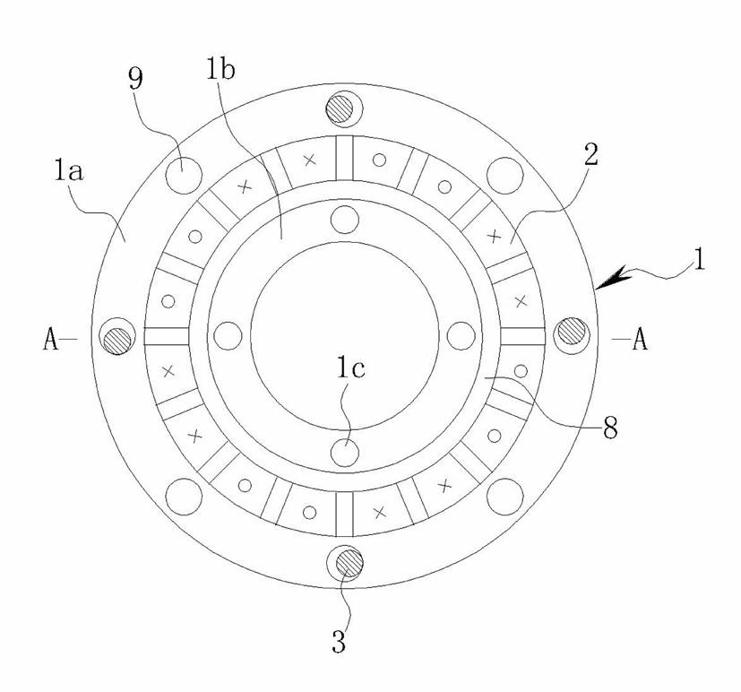
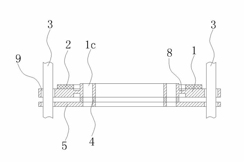
The invention discloses a travelling-wave linear ultrasonic micromotor which belongs to the technical field of ultrasonic motors and is mainly characterized by comprising a stator, wherein the stator is shaped as an annular hollow slice, and a piezoelectric ceramic ring is arranged on the surface of the stator; driving mechanisms are distributed on the outer edge of the stator, the lateral edges of the driving mechanisms are provided with a plurality of guide rails along the axial direction of the stator, and the driving mechanisms correspond to and is in contact with the guide rails; and a pretightening mechanism is connected to one end surface of the stator and in contact with the guide rails. The invention aims at providing the travelling-wave linear ultrasonic micromotor which has the advantages of compact structure, small occupying space, stability of working and high precision and is suitable for the aspects of optical lens, biology, medical treatment, micromachine, the science and technology for national defense, and the like.
Description
Traveling Wave Linear Ultrasonic Micromotor technical field The invention relates to an ultrasonic micromotor, more specifically, to a traveling wave linear ultrasonic micromotor. Background technique Ultrasonic motors use the inverse piezoelectric effect of piezoelectric materials to convert electrical energy into vibration energy of the ultrasonic motor stator, and then convert it into rotation or linear motion of moving parts through friction. It is generally mainly composed of functional components such as a stator, a rotor (mover) and a pre-pressure mechanism. Compared with traditional electromagnetic motors, ultrasonic motors have many unique features and advantages, such as: (1) Compact structure, high energy density (torque / mass), and easy miniaturization of the motor; (2) Low speed and high torque, without gear reduction mechanism, can realize direct drive; (3) The motor responds quickly, and can realize power-off self-locking; (4) Good position and speed ...
Claims
Login to View More Application Information
Patent Timeline
 Patent Type & Authority Applications(China)
IPC IPC(8): H02N2/08
Inventor 钟侃生廖进华张发强张礼
Owner GUANGDONG JIAHE MICROMOTOR
Features
- R&D
- Intellectual Property
- Life Sciences
- Materials
- Tech Scout
- Unparalleled Data Quality
- Higher Quality Content
- 60% Fewer Hallucinations
Learn More Browse by: Latest US Patents, China's latest patents, Technical Efficacy Thesaurus, Application Domain, Technology Topic, Popular Technical Reports.
© 2025 PatSnap. All rights reserved.Legal|Privacy policy|Modern Slavery Act Transparency Statement|Sitemap|About US| Contact US: help@patsnap.com


