Flow guiding riffle
A technology of two dividers and deflectors, which is applied in the field of two dividers, can solve the problems of inability to achieve uniform material distribution, uneven material distribution, and difficult to clean, and achieves easy cleaning, enhanced shrinkage effect, and improved shrinkage accuracy. Effect
Inactive Publication Date: 2011-06-15
CHANGSHA KAIYUAN INSTR
View PDF5 Cites 14 Cited by
- Summary
- Abstract
- Description
- Claims
- Application Information
AI Technical Summary
Problems solved by technology
In the process of sliding the sample into the rotary material catcher 14, it is easy to have uneven material distribution
Whether the existing shrinkage device can shrink the sample evenly depends on the uniformity of the sample flow. If the staff loads the sample flow into the feed hopper 11 at an uneven speed, the sample flow will enter the rotary feeder. The amount of each fan-shaped container of 14 is also different, so it is impossible to achieve the effect of uniform material distribution; and, after use, since the rotary feeder 14 is composed of a plurality of fan-shaped containers, it is very difficult to clean up. If it is not cleaned properly, it will affect the next use
Method used
View moreImage
Smart ImageViewing Examples

Examples
Embodiment Construction
Login to View More PUM
 Abstract
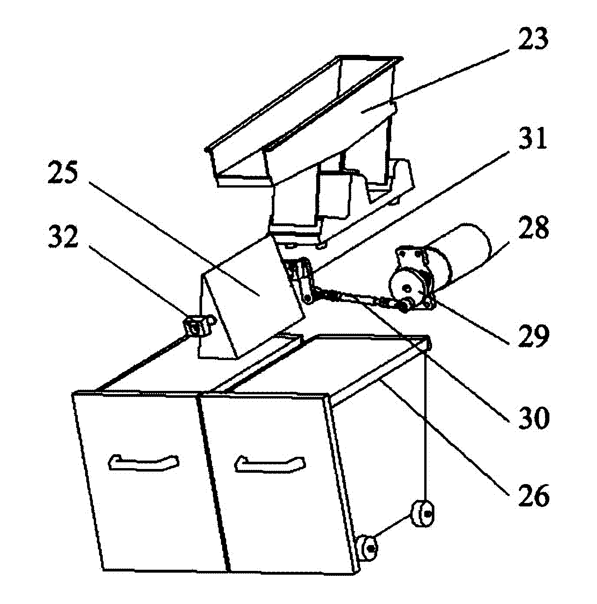
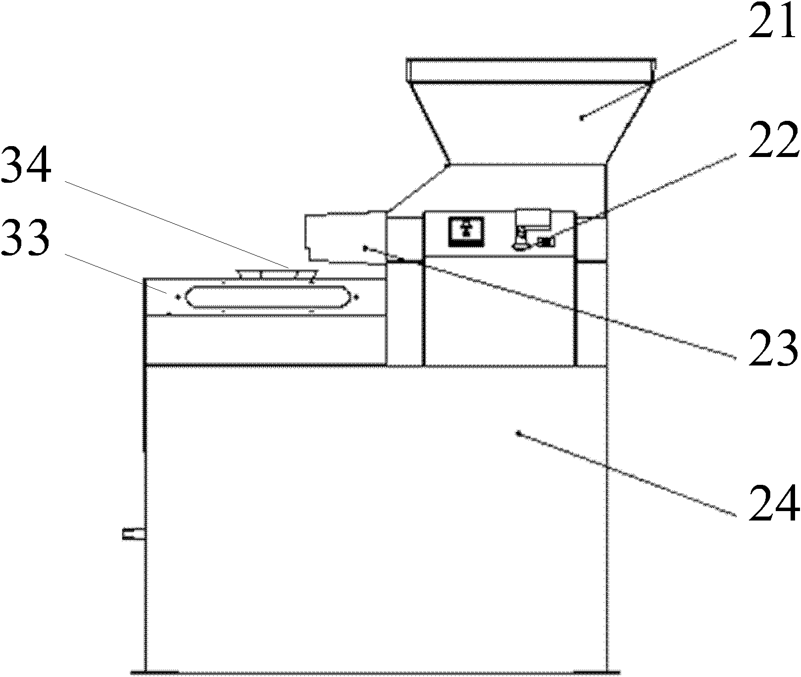
The invention discloses a flow guiding riffle, comprising: a frame; a feeding hopper mounted on the top of the frame; a uniform feeder arranged at the lower part of the outlet of the feeding hopper and on the frame; a flow guiding plate arranged below the outlet of the uniform feeder; a rotating shaft arranged inside the flow guiding plate, wherein one end of the rotating shaft is connected with a power device through a transmission device; receiving hoppers arranged at two sides of the lower part of the flow guide plate; and a control system arranged at the outside of the the frame. By adopting the uniform feeder and the flow guide plate, the flow guiding riffle can uniformly divide a fed sample into two parts which then fall into the receiving hopper, thus the flow guiding riffle raises the division precision and strengthens the division effect, furthermore, the receiving hopper can be cleaned more easily since the receiving hopper is not required to be configured as a rotary receiver consisting of a plurality of sector containers.
Description
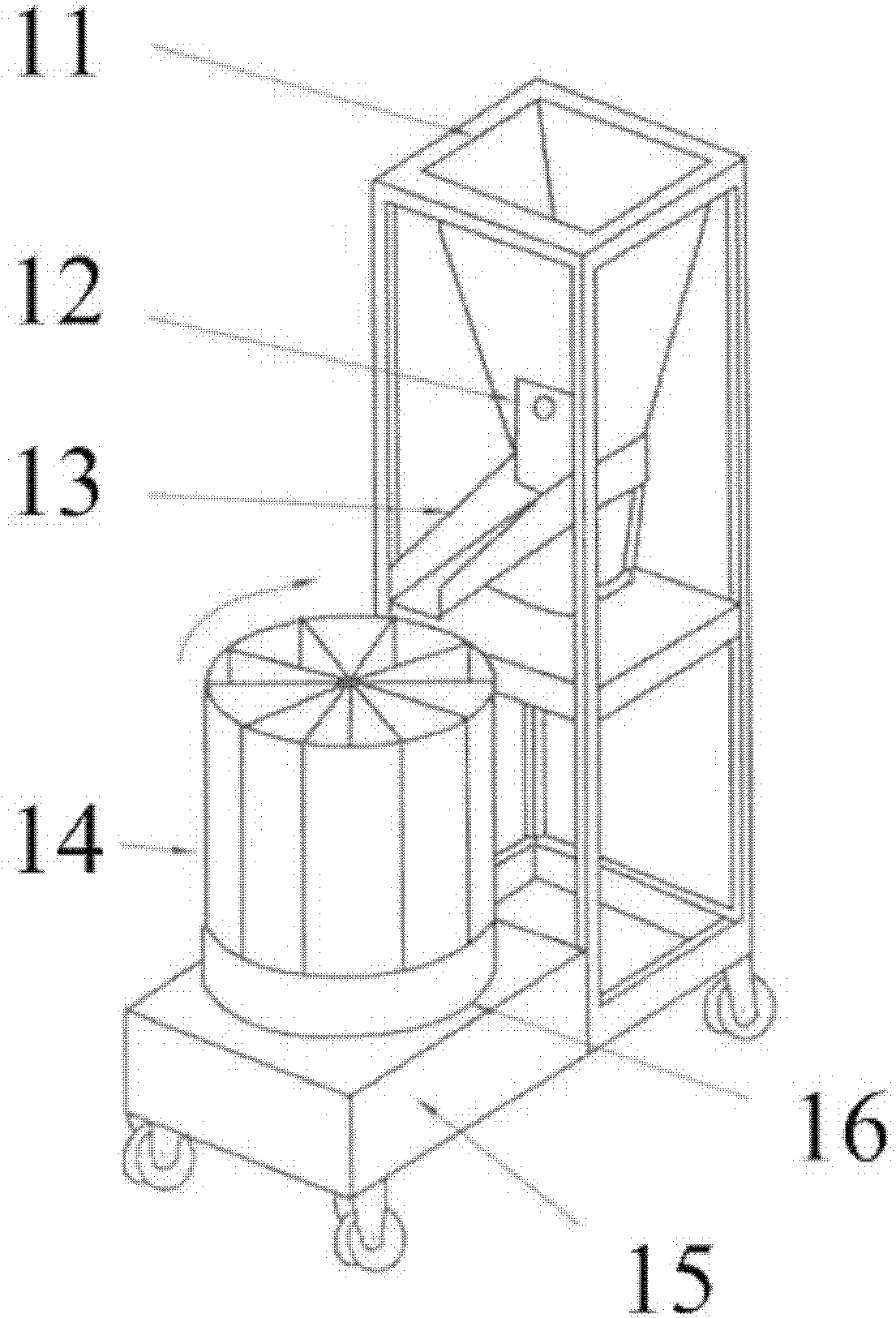
A diversion type splitter technical field The invention relates to the field of splitters, more specifically, to a flow-guiding splitter. Background technique The shrinking device is designed according to the provisions of the national standard GB474 "Preparation Method of Coal Samples", and is an indispensable tool for shrinking coal samples. Its main features are reasonable structure, easy to use, suitable for shrinkage sampling of coal, ore samples or other inhomogeneous granular materials. Please refer to Figure 1, which is a schematic diagram of an existing shrinking device, which includes a feed hopper 11, a discharge door 12, a discharge chute 13, a rotary material receiver 14, and a motor 15 And the turntable 16, wherein, the sample enters from the feed hopper 11, passes through the discharge door 12, and slides into the rotary material receiver 14 from the discharge chute 13, and the sample is divided by a plurality of fan-shaped containers of the rotary materia...
Claims
Login to View More Application Information
Patent Timeline
 Patent Type & Authority Applications(China)
IPC IPC(8): B65G47/46
Inventor 罗建文文胜邬茂
Owner CHANGSHA KAIYUAN INSTR
Features
- R&D
- Intellectual Property
- Life Sciences
- Materials
- Tech Scout
- Unparalleled Data Quality
- Higher Quality Content
- 60% Fewer Hallucinations
Learn More Browse by: Latest US Patents, China's latest patents, Technical Efficacy Thesaurus, Application Domain, Technology Topic, Popular Technical Reports.
© 2025 PatSnap. All rights reserved.Legal|Privacy policy|Modern Slavery Act Transparency Statement|Sitemap|About US| Contact US: help@patsnap.com