
Method for manufacturing hand tool handle, and a hand tool handle

A technology for hand tools and handles, which is applied in the field of manufacturing hand tool handles. It can solve problems such as quality changes and unpredictable deformations, and achieve the effect of easy parts transfer and reduced quality changes.

Active Publication Date: 2011-06-15
FISKARS FINLAND OY
View PDF3 Cites 3 Cited by
  • Summary
  • Abstract
  • Description
  • Claims
  • Application Information

AI Technical Summary

Problems solved by technology

In other words, the deformation is usually not predictable, which leads to mass variation

Method used


Image

  • Method for manufacturing hand tool handle, and a hand tool handle
  • Method for manufacturing hand tool handle, and a hand tool handle
  • Method for manufacturing hand tool handle, and a hand tool handle

Examples


Embodiment Construction

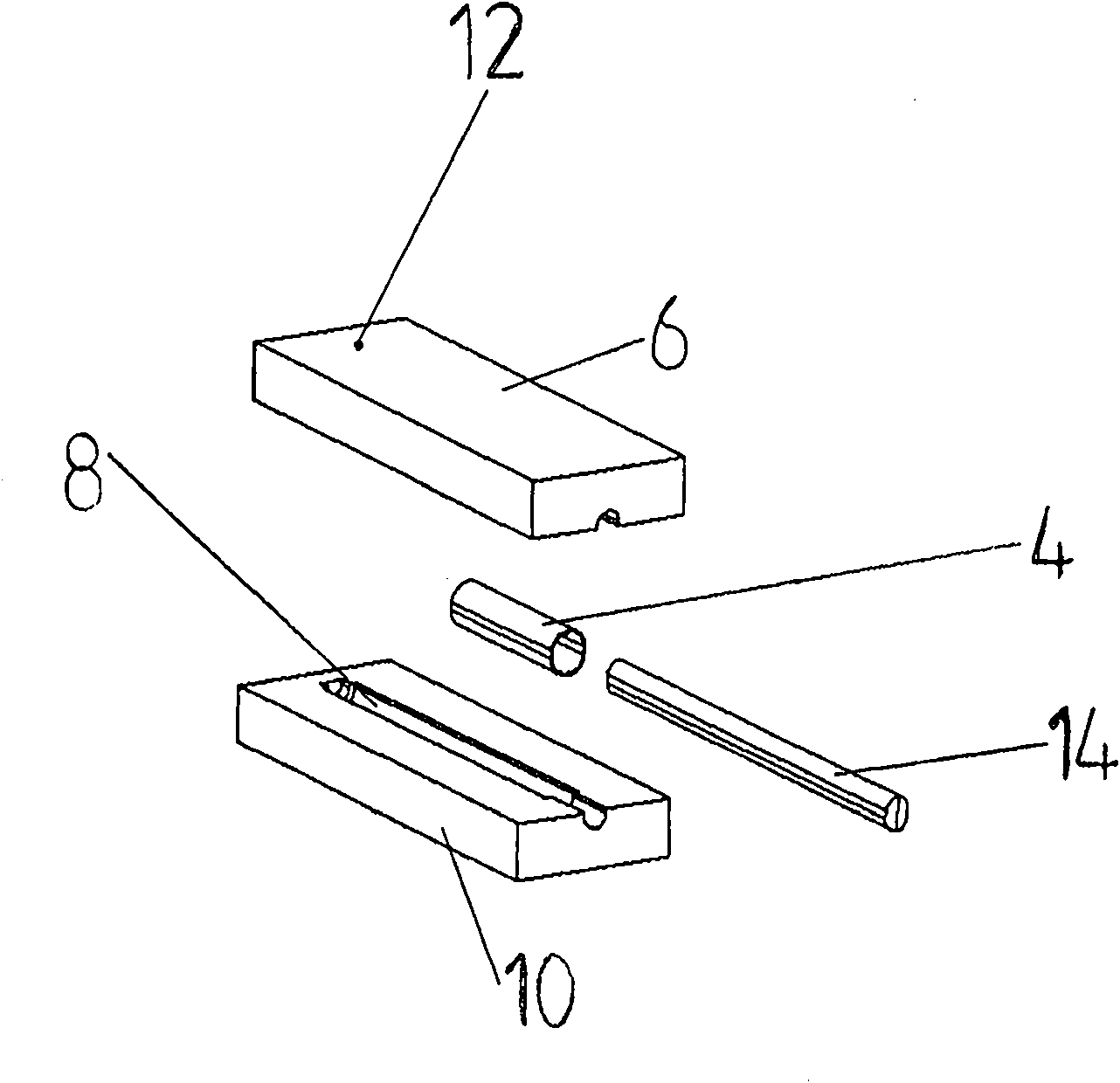
[0016] refer to figure 1 , which shows a schematic diagram of the apparatus required in the method for manufacturing the handle of the invention and the first step of the method. according to figure 1 , first make the surface part 4. The surface part 4 can be manufactured, for example, by injection molding in a separate surface part mould, or alternatively, by other molding techniques or other manufacturing methods. according to figure 1 , the surface portion 4 can be a sleeve-like or tubular part, a planar part, a strip-like part or any other part which can be arranged on the surface of the body part of the handle. The sleeve-like surface portion 4 is manufactured to at least partially surround the body portion 2 in the final product. Preferably, the surface portion 4 is a grip portion which the user holds when using the hand tool. The surface portion or grip portion 4 is preferably of a softer material than the body portion on which the surface portion is arranged.

[...


PUM


Abstract

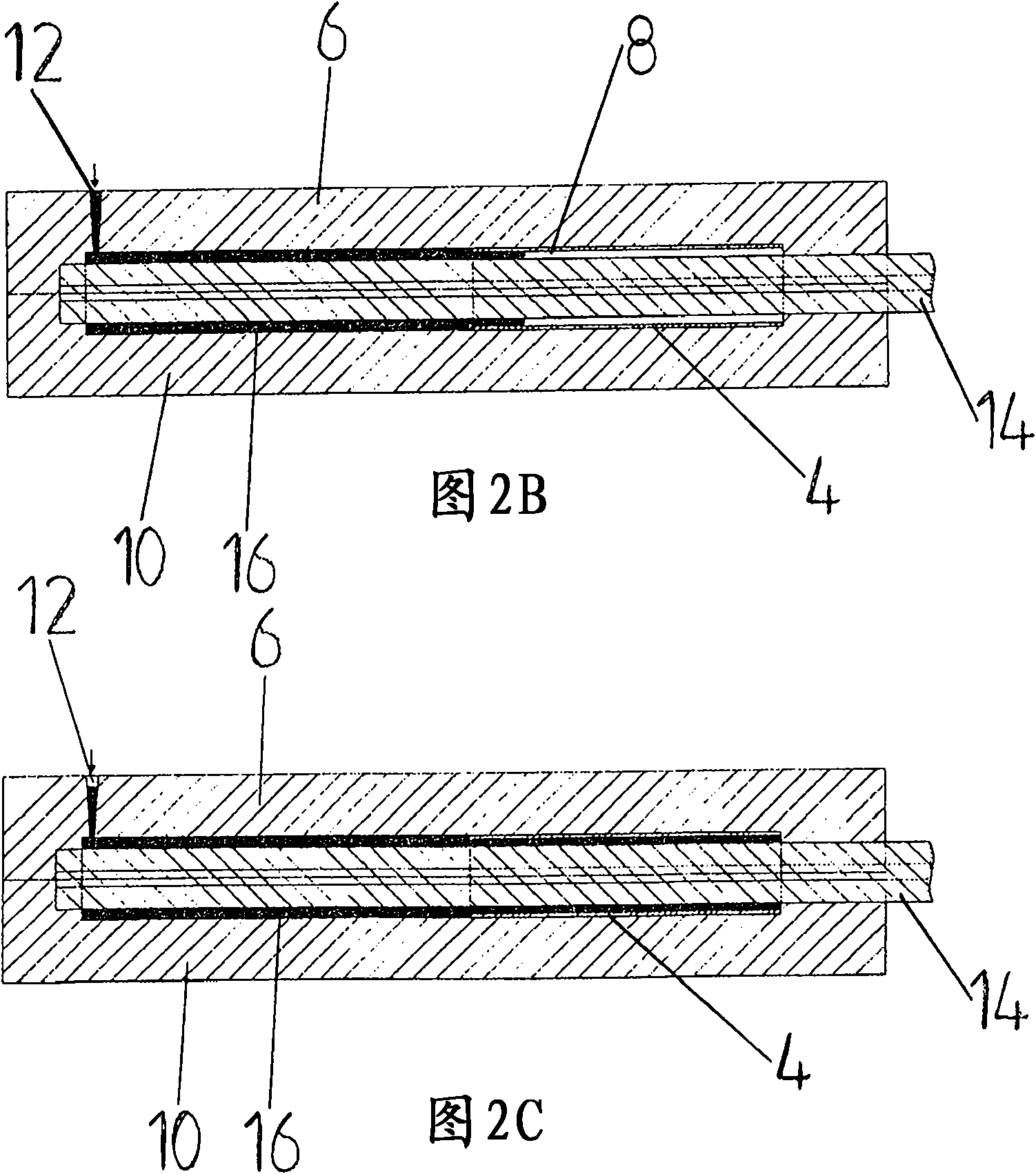
The present invention relates to a method for manufacturing a handle for a hand tool, the handle comprising a body portion and a gripping part that is provided at least partly on the body portion and intended for the user to grip when using the hand tool. In the method of the invention there is first fabricated the gripping part and it is set in a mould cavity, whereafter melt mass is cast into the mould cavity to provide the body portion such that the melt mass flows underneath the gripping part, whereby the gripping part is pressed against the wall of the mould cavity.

Description

technical field [0001] The invention relates to a method for manufacturing a handle of a hand tool. Background technique [0002] Hand tool handles are typically manufactured from two or more materials, or from two or more interconnected parts. These handles generally comprise a rigid body portion and one or more surface portions disposed thereon. The body part is larger in size and harder in material and it forms the body of the handle to which other parts of the hand tool are connected or connectable. The surface portion is in turn generally arranged on the body portion as a surface layer covering at least a portion of the body portion. The surface portion is smaller in size than the body portion and is generally of a softer material than the body portion. The surface portion may for example be a grip portion, the purpose of which is to provide a grip area for the handle which the user grips when using the hand tool in order to hold the hand tool. The grip portion is t...

Claims


Application Information

Patent Timeline
Patent Type & Authority Applications(China)
IPC IPC(8): B29C45/00B25G1/00
CPCB29C45/1676B29C45/14598B25G1/01B25G3/34B29C45/14475
Inventor 卡尔奥洛夫·霍尔姆
Owner FISKARS FINLAND OY
Learn More