
Transitional track planning method for welding robot

A welding robot and trajectory planning technology, applied in welding equipment, metal processing equipment, manufacturing tools, etc., can solve the problems of not considering the error of the transition section, not considering the transition problem, and difficult to quickly switch between different trajectories.

Inactive Publication Date: 2012-12-05
CHANGSHA HONGDIAN AUTOMATION TECH
View PDF1 Cites 0 Cited by
  • Summary
  • Abstract
  • Description
  • Claims
  • Application Information

AI Technical Summary

Problems solved by technology

The above trajectory planning methods have not studied the switching and transition between different trajectories, so it is difficult for the robot to quickly switch to different trajectories to work during the welding process. The transition between different trajectories is a hot spot and difficulty in robot trajectory planning. The problem is that the direct error between the transition section and the ideal trajectory is not considered in the prior art, but these errors may be key parameters in some applications, such as robotic arc welding
The transition between straight lines and other shapes (such as arcs) is not considered

Method used


Image

  • Transitional track planning method for welding robot
  • Transitional track planning method for welding robot
  • Transitional track planning method for welding robot

Examples


Embodiment Construction

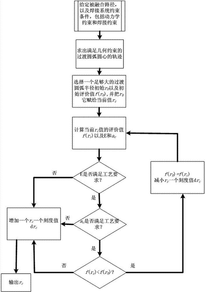
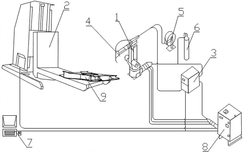
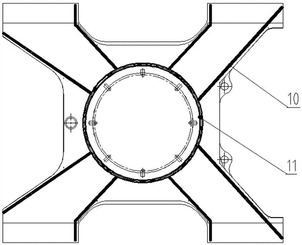
[0045] The present invention will be further described below in conjunction with a 6-DOF robotic arc welding system. The flow chart of welding robot transition trajectory planning is shown in figure 1 As shown, the transition trajectory planning steps are as described above in the content of the invention in this specification. Such as figure 2 As shown, the robot arc welding system consists of an industrial robot 1, a positioner 2, a welding power supply 3, a welding torch 4, a wire feeding mechanism 5, a gas source 6, a control center 7, and a control cabinet 8. Robot 1 is a standard 6-degree-of-freedom industrial robot, and positioner 2 is an L-shaped positioner. Fix the workpiece assembled by spot welding on the working table with T-shaped slots with a pressure plate and T-shaped bolts. The rotation speed can be turned over to the desired position and then lifted to a suitable height to perform welding on the workpiece 9. For the circular welding seam of the rotation, t...


PUM


Abstract

The invention discloses a transitional track planning method for a welding robot. The transitional track is used for fusing a straight segment welding line and an arc segment welding line, geometric constraint conditions of adjacent fused straight segment welding line and fused arc segment welding line of a workpiece to be welded are imported into a robot path planning module to generate a transitional segment arc welding line track, and by controlling the arc radius of the transitional segment track, welding constraint conditions and robot welding system dynamic constraint conditions are metwhen the robot welds the transitional segment. The track planning method is suitable for switching different segments of tracks and planning transitional tracks, and solves the problem of smoothness of transiting from the straight segment welding line to the arc segment welding line when the robot performs arc welding.

Description

technical field [0001] The invention relates to a robot transition trajectory planning method, in particular to a welding robot trajectory planning method. Background technique [0002] With the development of advanced manufacturing technology, it has become an inevitable trend to realize the automation, flexibility and intelligence of welding product manufacturing. The trajectory planning of the robot is usually completed in the Cartesian coordinate system, because the tasks of the robot are usually completed in the task space, and the realization of the barrier function is easier, but the trajectory planning of the robot is usually realized in the joint space , after the geometric trajectory of the robot is generated in the Cartesian coordinate system, it is converted into the joint trajectory in the key space of the robot through inverse kinematics calculation. [0003] At present, there are some studies on the trajectory planning method of welding robots, such as: Chine...

Claims


Application Information

Patent Timeline
Patent Type & Authority Patents(China)
IPC IPC(8): B23K31/02
Inventor 汤哲张立彭浩明陈华荣周建勇
Owner CHANGSHA HONGDIAN AUTOMATION TECH
Learn More