
Integrated system for utilizing residual heat of boiler smoke and removing sulfur

A technology for boiler flue gas and waste heat, which is applied to furnaces, waste heat treatment, furnace components, etc., can solve the problems of no flue gas waste heat, inability to realize deep utilization of flue gas waste heat, etc., and achieve the effect of reducing water consumption and improving boiler efficiency.

Inactive Publication Date: 2014-04-09
NORTH CHINA ELECTRIC POWER UNIV (BAODING)
View PDF12 Cites 3 Cited by
  • Summary
  • Abstract
  • Description
  • Claims
  • Application Information

AI Technical Summary

Problems solved by technology

[0005] CN101586803A discloses a waste heat utilization system arranged between the dust collector and the desulfurization system, with low-pressure gas-saving gas as the heat-absorbing main body. The flue gas temperature at the outlet of the heat exchanger is ≥80°C, and the waste heat of the flue gas is not fully utilized. Enamel or The nickel-based alloy permeation layer is corrosion-resistant steel, and anti-corrosion measures affect heat transfer; CN86105222A discloses a low-pressure economizer composite system that adopts a surface type or heat pipe heat exchanger arranged behind an air preheater, but utilizes flue gas temperature Higher, can not realize the deep utilization of flue gas waste heat; CN108745A discloses a low-pressure economizer composite system arranged in front of the air preheater, which can realize the best matching selection of the condensate amount to the low-pressure economizer through the regulating valve, but using The temperature of the flue gas is high, and the deep utilization of the waste heat of the flue gas cannot be realized; CN1104755A discloses a method for recovering waste heat from an acid-resistant heat exchanger. Combination of wet flue gas desulfurization system

Method used


Image

  • Integrated system for utilizing residual heat of boiler smoke and removing sulfur
  • Integrated system for utilizing residual heat of boiler smoke and removing sulfur

Examples


Embodiment Construction

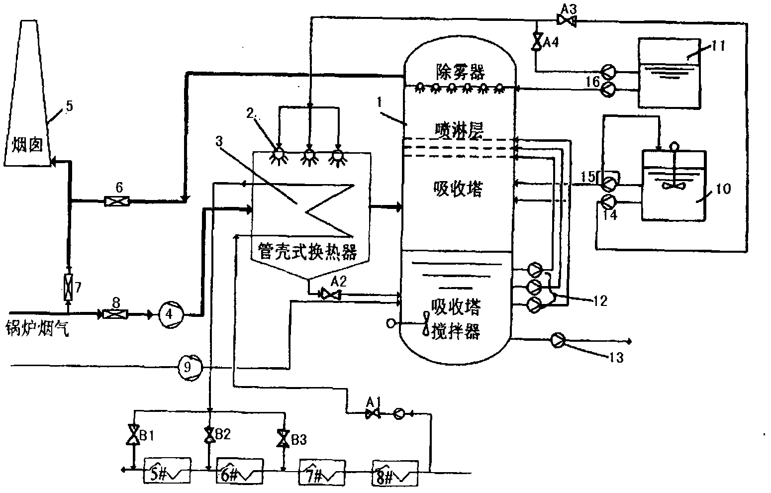
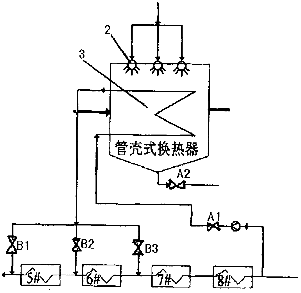
[0013] The invention provides an integrated system for boiler flue gas waste heat utilization and desulfurization. The present invention will be further described below in conjunction with the accompanying drawings and embodiments. exist figure 1 In the integrated system diagram of boiler flue gas waste heat utilization and desulfurization shown in the figure, the system takes the shell-and-tube heat exchanger 3 as the heat exchange main body, and is arranged between the booster fan (or boiler induced draft fan) 4 and the desulfurization absorption tower 1 tail flue. The flue gas in the shell-and-tube heat exchanger 3 is exothermic working medium, and the flue gas flows into the shell-and-tube heat exchanger 3 from the booster fan (or boiler induced draft fan) 4, and is connected to the lower part of the desulfurization absorption tower 1 through the A2 valve; The water side of the shell-and-tube heat exchanger 3 is a heat-absorbing working medium, and its inlet comes from b...


PUM


Abstract

The invention relates to an integrated system for utilizing residual heat of boiler smoke and removing sulfur. A tubular heat exchanger is used as a heat exchange main body of the system and is arranged on a tail flue between a booster fan and a desulfurization absorber, wherein the tubular heat exchanger is connected to a condensed water heating system; sets of nozzles are arranged in the heat exchanger for intermittently washing the inner tube wall of the heat exchanger and the wall of the flue; the processing water from a desulfurization system or limestone size or the mixture of the processing water and the limestone size are used as washing fluid for washing the walls; and the washing fluid is recovered and reused by returning to the desulfurization absorber after gathering on the bottom of the heat exchanger. By using the integrated system provided by the invention, the temperature of the smoke on the tail part of the boiler can be reduced to 50-70DEG C, thereby recovering the residual heat of boiler smoke and increasing the boiler efficiency. Meanwhile, the smoke within the temperature range which enters into the absorber of the desulfurization system on the tail part still meets the requirement of the temperature for desulfurization reaction, and the water consumption for desulfurization is reduced by 50-80%. Without designing a single size preparation and sewage treatment process, the water-saving and energy-saving properties, the anticorrosion property and reuse of the whole system are finally realized.

Description

technical field [0001] The invention belongs to the scope of boiler flue gas waste heat desulfurization system, and in particular relates to a boiler flue gas waste heat utilization and desulfurization integrated system which fully utilizes boiler waste heat, saves energy and water, and meets the requirements of desulfurization. Background technique [0002] At present, the exhaust gas temperature of various boilers is relatively high, especially for large-scale power plant boilers. The temperature of the flue gas at the outlet of the desulfurization system booster fan (or the outlet of the induced draft fan) is about 120-160°C. It can significantly improve the efficiency of the boiler and the whole plant, but at the same time, it will also cause the flue gas temperature to be lower than the acid dew point and water dew point of the flue gas, which will cause the acid liquid to condense on the heat exchanger tube wall and the flue wall, and severely corrode the tube In addit...

Claims


Application Information

Patent Timeline
Patent Type & Authority Patents(China)
IPC IPC(8): B01D53/78F23J15/04F27D17/00
CPCY02P10/25Y02P80/15
Inventor 徐钢杨勇平杨志平田瑶查永龙田龙虎
Owner NORTH CHINA ELECTRIC POWER UNIV (BAODING)
Learn More