Simple line spanning frame

A technology of spanning racks and lines, applied in the direction of overhead lines/cable equipment, etc., can solve the problems of inconvenient traffic and residents' life, high work intensity of construction personnel, and the arc of the spanning line cannot be reached, and can increase the height of the side bar and the spanning bar. The effect of length, reduction of cross labor intensity, and strong versatility

Inactive Publication Date: 2011-06-01
NANYANG POWER SUPPLY COMPANY OF STATE GRID HENAN ELECTRIC POWER
View PDF3 Cites 9 Cited by
  • Summary
  • Abstract
  • Description
  • Claims
  • Application Information

AI Technical Summary

Problems solved by technology

[0002] Crossing wiring is often encountered in roads, rivers, mountainous areas, densely populated areas and other environments during line construction. For example, roads, buildings and other live lines are often encountered during the construction of 35KV, 10KV, and 400V lines. The erection is affected by the terrain, traffic environment, population density, etc. It is difficult to erect, and it brings inconvenience to traffic and residents' lives. It takes a long time to erect the spanning frame during the construction process. The construction personnel must work at heights and must climb before crossing the line. Go to the top of the spanning frame to fasten the spanning line. After the spanning line passes the spanned line, it must go to the top of the spanning frame to remove the spanning line. The work intensity of the construction personnel is high, there are potential safety hazards, and the overall construction cost is high
When the crossing distance is long, there is a danger that the crossing line accidentally falls off to the live line being crossed or the arc of the crossing line is too large to reach the safe distance from the live line being crossed, resulting in a vicious accident

Method used


Image

  • Simple line spanning frame
  • Simple line spanning frame
  • Simple line spanning frame

Examples


Embodiment Construction

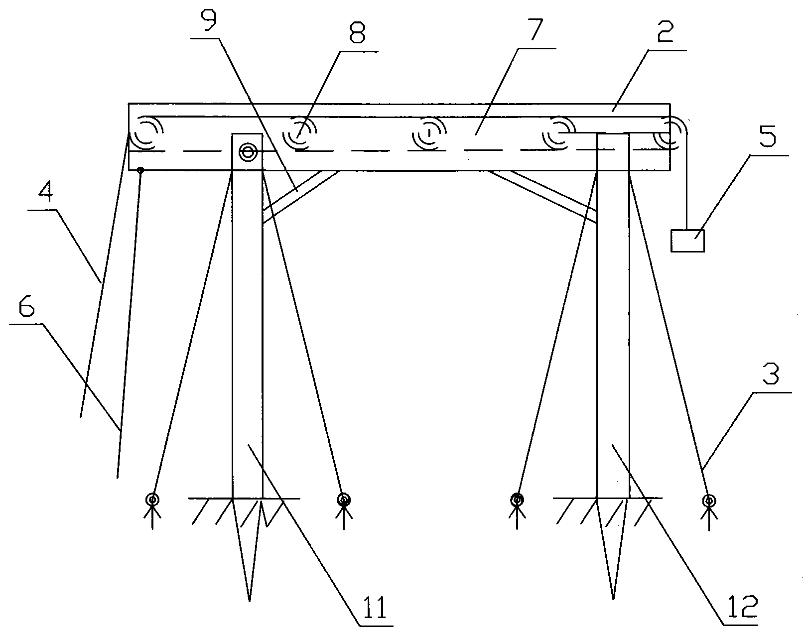
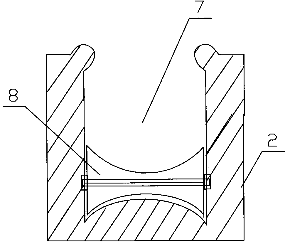
[0010] like figure 1 As shown, a simple line spanning frame includes two uprights 11, 12 and a spanning rod 2, the spanning bar 2 is axially connected with one of the uprights 11, and is connected with the other upright 12 in a card-type manner. A fixed pull wire 3 is arranged on the uprights 11 and 12, a long groove 7 is longitudinally arranged on the upper surface of the spanning rod 2, a plurality of pulleys 8 are arranged in the long groove 7, and a pull wire 4 is arranged on the pulley 8 to pass through the span The rod slot 7 extends out of the spanning rod 2 , one end of the traction wire 4 is provided with a counterweight 5 , and one end of the spanning rod 2 that is axially connected with the upright column 11 is provided with a pulling rope 6 .

[0011] A support rod 9 is arranged between the upright columns 11 and 12 and the spanning rod 2 .

[0012] When using, assemble the side column 11 and the spanning rod 2, put the traction wire 4 and the connected counterwei...


PUM


Abstract

The invention discloses a simple line spanning frame which comprises two stand columns and a spanning rod, wherein the spanning rod is connected with one stand column through a shaft and connected with the other stand column in a clamping manner, fixed bracing wires are arranged on the stand columns, the upper surface of the spanning rod is longitudinally provided with an elongated slot, a plurality of pulleys are arranged in the elongated slot, each pulley is provided with a draught line penetrating through the elongated slot of the spanning rod and extending out of the spanning rod, one end of the draught line is provided with a balance weight, and one end of the spanning rod, which is connected with the stand column through the shaft, is provided with a digging rope. The line is spanned by using the simple spanning frame, and requirements on various spanning environments can be met. The spanning frame has the advantages of simple structure, light weight, convenience and flexibility for operation, strong generality, safety in spanning, no hidden dangers, and convenience and simpleness for transportation and assembly. The working at height can be carried out by constructors without climbing up and down the spanning frames.

Description

technical field [0001] The invention belongs to the technical field of electric construction auxiliary equipment, and particularly relates to a simple line spanning frame. Background technique [0002] Crossover wiring is aimed at the environment of roads, rivers, mountainous areas, densely populated areas, etc. that are often encountered in line construction, such as highways, buildings and other live lines often encountered during the construction of 35KV, 10KV, 400V lines. Affected by terrain, traffic environment, population density, etc., erection is difficult, and brings inconvenience to traffic and residents' lives. It takes a long time to erect spanning spans during the construction process, and construction personnel must work at high altitudes and climb before spanning lines. Fasten the straddle line to the top of the straddle frame. After the straddle line passes the straddled line, the straddle line must be removed from the top of the straddle frame. The work inte...

Claims


Application Information

Patent Timeline
IPC IPC(8): H02G1/02
Inventor 严君国李勇刚黄国玺谢有刚
Owner NANYANG POWER SUPPLY COMPANY OF STATE GRID HENAN ELECTRIC POWER
Why Eureka
Try Eureka