Pneumatic tire

A technology for pneumatic tires and carcasses, which is applied to the reinforcement layers, tire parts, tire edges and other directions of pneumatic tires, can solve problems such as poor ride comfort, and achieve the effect of superior ride comfort.

Inactive Publication Date: 2011-06-01
SUMITOMO RUBBER IND LTD
View PDF4 Cites 0 Cited by
  • Summary
  • Abstract
  • Description
  • Claims
  • Application Information

AI Technical Summary

Problems solved by technology

Tires with greater longitudinal stiffness have poorer ride comfort

Method used


Image

  • Pneumatic tire
  • Pneumatic tire
  • Pneumatic tire

Examples


Embodiment 1

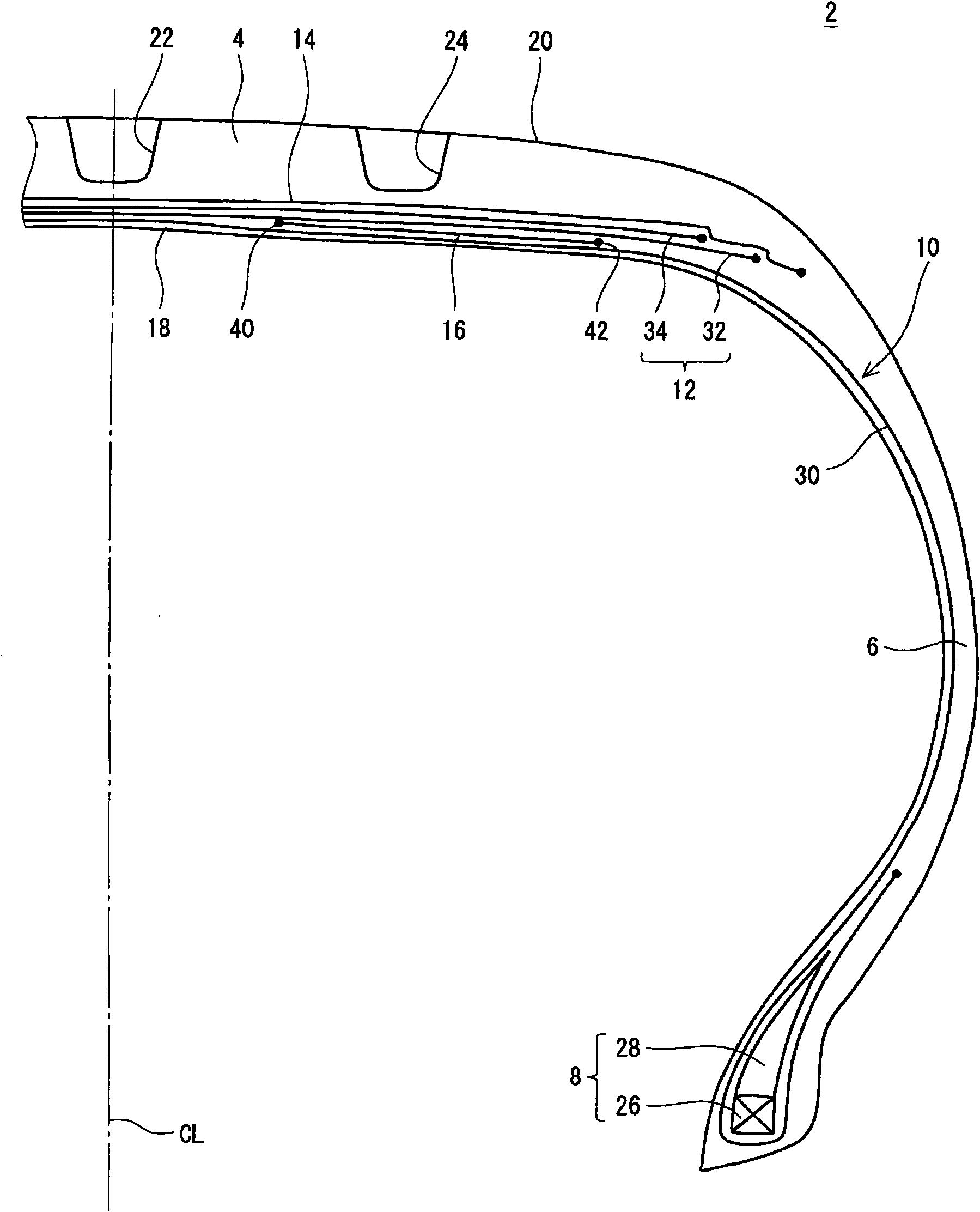
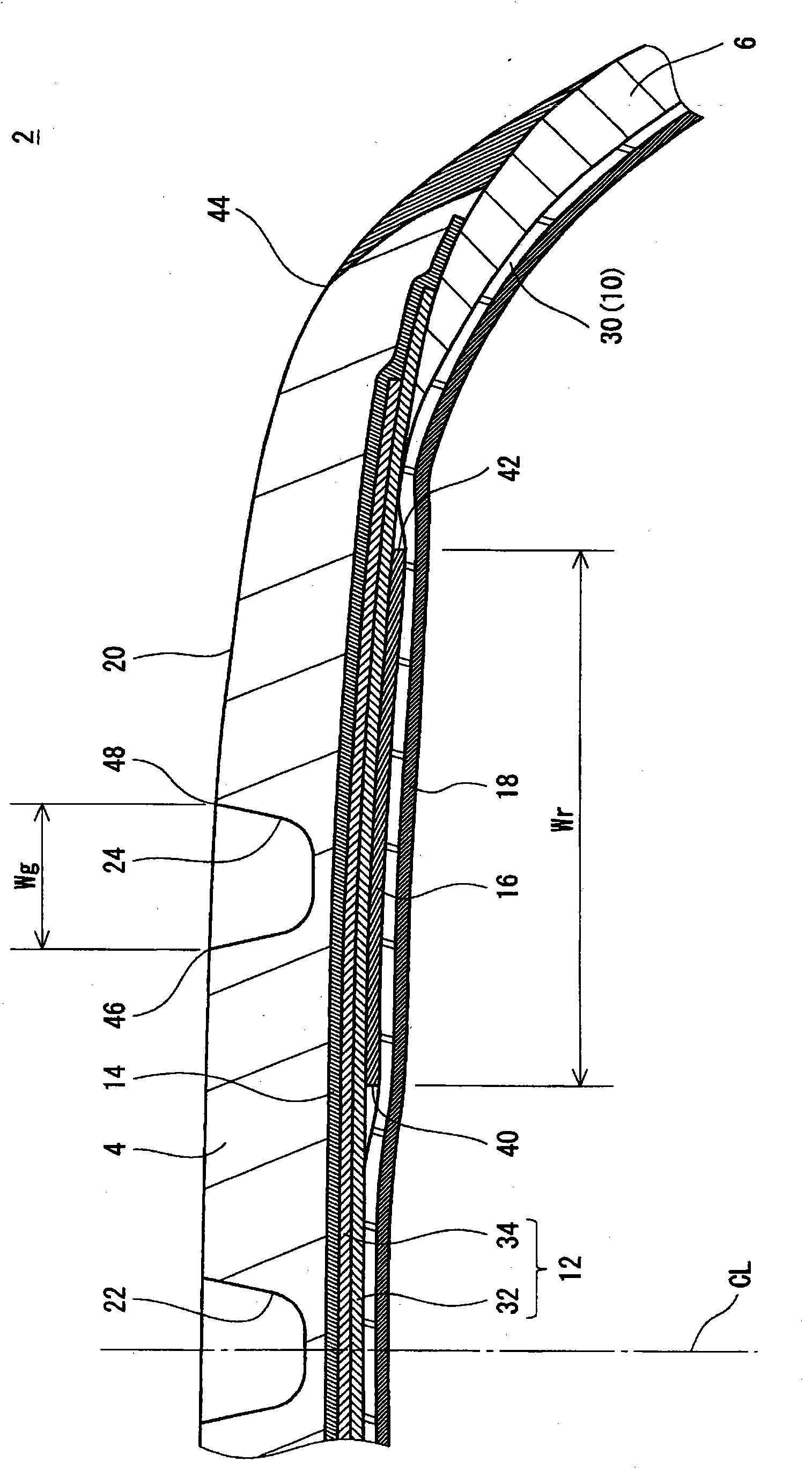
[0066] made Figure 1 to Figure 4 Said structure of the passenger car tires. The size of this tire is "195 / 65R15". The specifications of this tire are as follows.

[0067] Tread

[0068] Main groove width Wg: 8mm

[0069] Carcass

[0070] Cord Material: Nylon

[0071] Cord fineness: 1670 dtex / 2

[0072] The angle of the cord relative to the circumferential direction: 90°

[0073] belt layer

[0074] Cord Material: Steel

[0075] The composition of the cord: 2+2

[0076] Cord wire diameter: 0.23mm

[0077] The angle of the cord relative to the circumferential direction: 26°

[0078] belt layer

[0079] Cord Material: Nylon

[0080] Cord fineness: 1400 dtex / 2

[0081] The angle of the cord relative to the circumferential direction: about 0°

[0082] reinforcement layer

[0083] Cord Material: Steel

[0084] The composition of the cord: 2+2

[0085] Cord wire diameter: 0.23mm

[0086] The angle of the ...

Embodiment 2~8

[0089] Tires of Examples 2 to 8 were obtained in the same manner as in Example 1 except that the width Wr was set as shown in Table 1 below.

Embodiment 9~14

[0095] Tires of Examples 9 to 14 were obtained in the same manner as in Example 1 except that the position of the reinforcing layer was set as shown in Table 2 below. The meanings of symbols (A) to (E) in Table 2 are as follows.

[0096] (A) Between the carcass 10 and the belt 12

[0097] (B) Between the inner liner 18 and the carcass 10

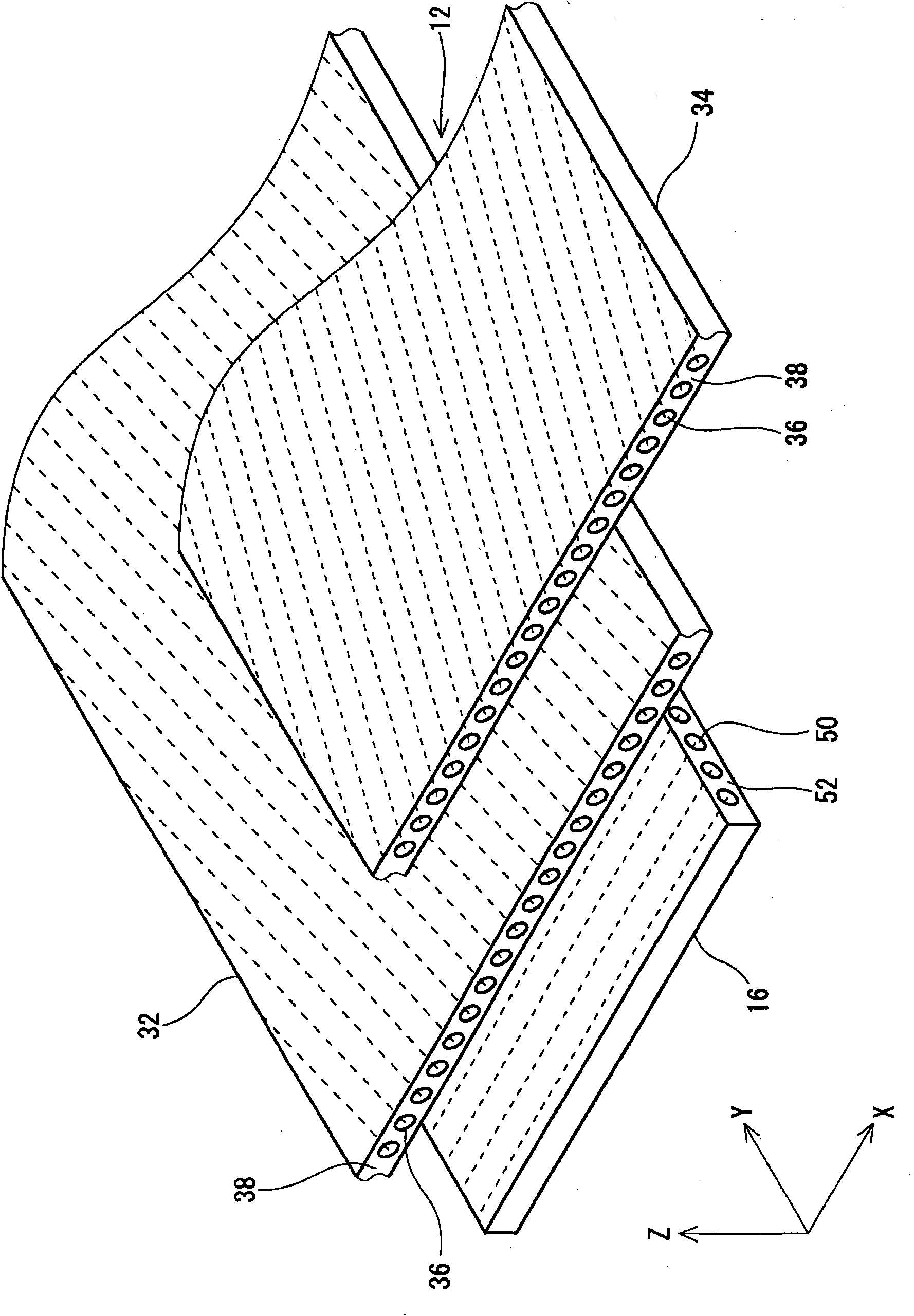
[0098] (C) Between the inner layer 32 of the belt layer 12 and the outer layer 34 of the belt layer 12

[0099](D) Between the belt layer 12 and the belt layer 14

[0100] (E) Between the belt layer 14 and the tread portion 4


PUM


Abstract

The invention provides a pneumatic tire (2), having excellent operation stability and driving comfortability and benefitting low oil consumption of the vehicle. The pneumatic tire (2) includes a tread (4), a sidewall (6), a bead (8), a carcass (10), a belt (12), a band (14), a reinforcing layer (16), and an inner liner (18). The tread (4) has a shoulder main groove (24). The reinforcing layer (16) is present locally in an axial direction. The reinforcing layer (16) is positioned between the carcass (10) and the belt (12) in a radial direction. The reinforcing layer (16) is positioned on an inside in the radial direction with respect to the shoulder main groove (24). The reinforcing layer (16) is formed by a large number of cords provided in parallel and a topping rubber. The respective cords are extended substantially in the axial direction. A width (Wr) of the reinforcing layer (16) is equal to or higher than 200% of a width (Wg) of the shoulder main groove (24) and is equal to or lower than 500% of the width (Wg) of the shoulder main groove (24).

Description

technical field [0001] The present invention relates to a pneumatic tire mounted on a car or the like. Background technique [0002] A tire has a tread portion, a sidewall portion, a bead, a carcass, a belt, and the like. The belt layer includes an inner layer and an outer layer. The inner layer and the outer layer respectively include a plurality of cords and a topping arranged side by side. Each cord is inclined with respect to the equatorial plane. The belt contributes to the rigidity of the tire. [0003] The tread portion has a plurality of main grooves. Each main groove extends along the circumferential direction. This main ditch helps with drainage. The surface of the tread portion is divided by these main grooves. [0004] When a vehicle turns, centrifugal force acts on the vehicle. On the other hand, cornering creates lateral resistance on the tires. The magnitude of the lateral resistance depends on the coefficient of friction between the tread and the roa...

Claims


Application Information

Patent Timeline
Patent Type & Authority Applications(China)
IPC IPC(8): B60C9/18B60C9/28B60C15/04
CPCB60C2009/2041B60C9/2009Y10T152/10765
Inventor 松井博司和春亮
Owner SUMITOMO RUBBER IND LTD
Why Eureka
Try Eureka