
Lighting device and door lining using same

A lighting device and technology for projecting light, which is applied in the direction of car door lighting devices, vehicle interior lighting devices, light guides of lighting systems, etc., can solve the problems of complex structure and difficulty in achieving low prices, and achieve the goal of reducing discomfort and improving operability Effect

Inactive Publication Date: 2011-05-25
HONDA MOTOR CO LTD
View PDF5 Cites 22 Cited by
  • Summary
  • Abstract
  • Description
  • Claims
  • Application Information

AI Technical Summary

Problems solved by technology

[0004] However, in the linear light emitter of Patent Document 1 and the vehicle lighting device of Patent Document 2, it is necessary to use a linear light emitter or a branch light propagation path (optical fiber) for each lighting position.
For example, when projecting light from three positions, it is necessary to arrange three linear light emitters (light guides) or optical fibers (light guides), so the structure becomes complicated
[0005] In addition, for example, in the case of irradiating two positions, in order to make the luminance different from bright and dark, or to make the size of the irradiated area different depending on the object to be irradiated, it is necessary to manufacture two kinds of linear light emitters or optical fibers for each, making it difficult to reduce the price.

Method used


Image

  • Lighting device and door lining using same
  • Lighting device and door lining using same
  • Lighting device and door lining using same

Examples


Embodiment Construction

[0036] Hereinafter, preferred embodiments of the present invention will be described with reference to the drawings.

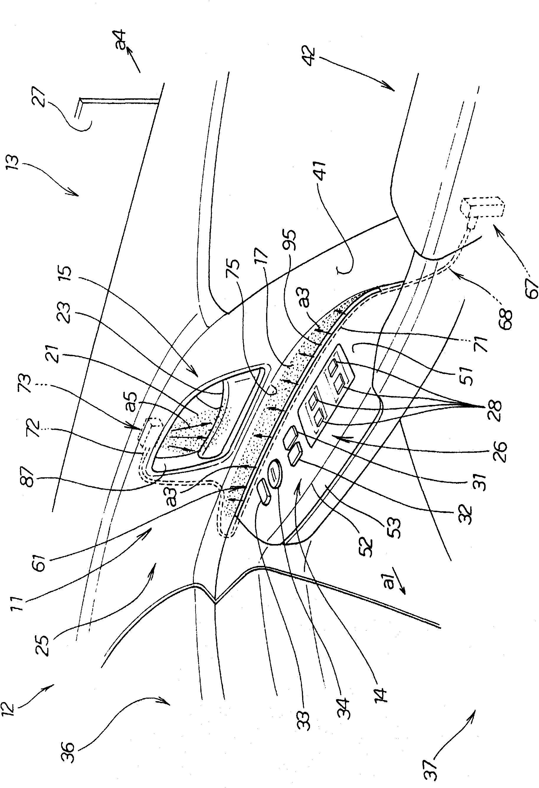
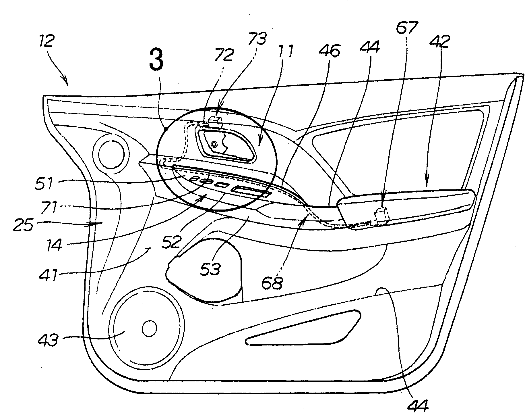
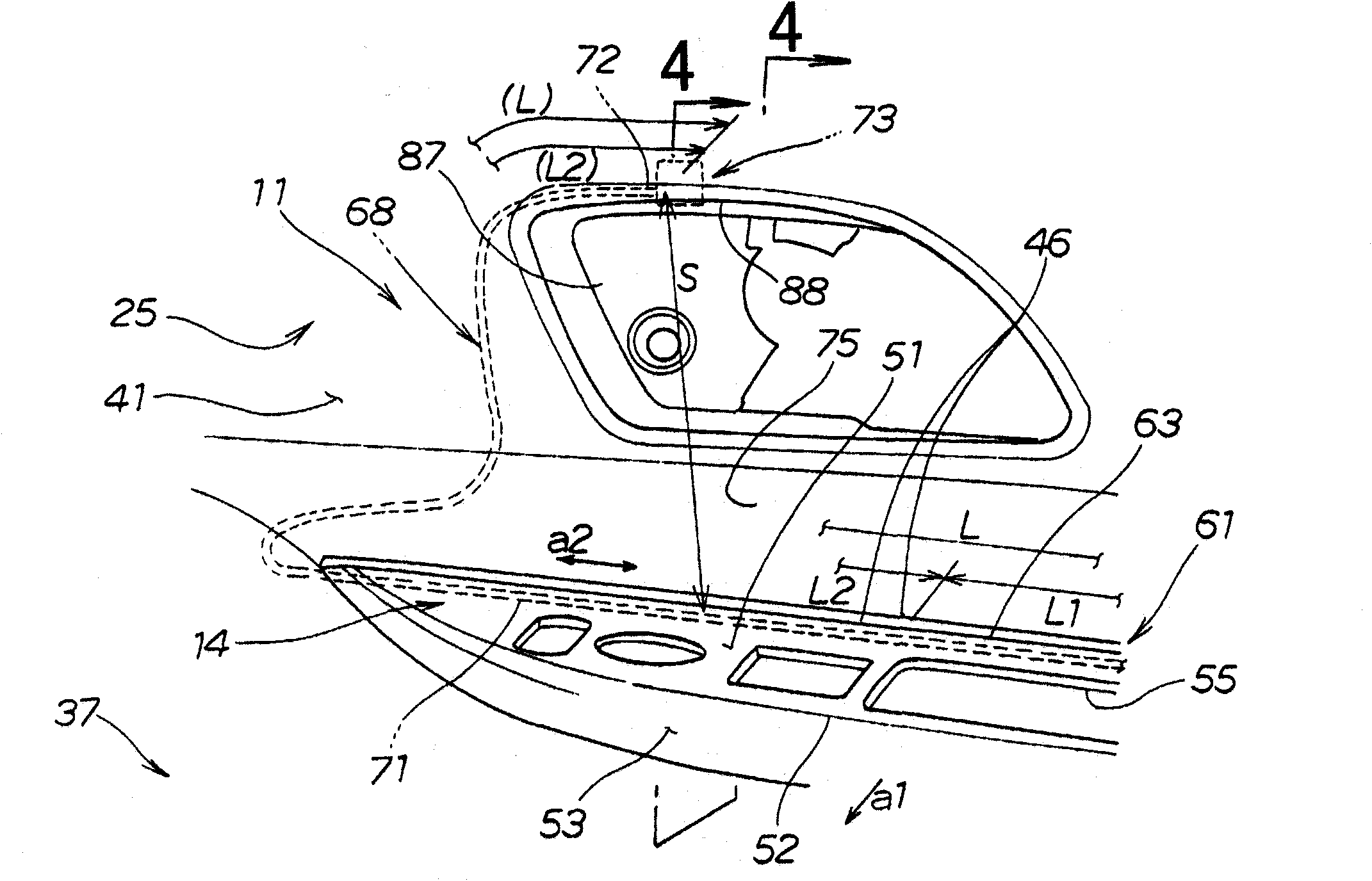
[0037] figure 1 The illustrated lighting device 11 always illuminates a switch panel 14 and an operating member (inner handle) 15 arranged on a door 13 of a vehicle 12 . It will be described in detail later, but the switch panel 14 is indirectly irradiated with the indirect light irradiated to the wider irradiated area 17 (the range shown by the dot pattern), and the smaller irradiated area 21 (the range shown by the dot pattern) is used to indirectly irradiate the switch panel 14 . The range of irradiated direct light directly irradiates the inner handle 15 .

[0038] The inner handle 15 is a conventional structure having an operation portion (door handle main body) 23 to be held when opening the right front door 13 . As generally observed, when the door handle main body 23 is held and pulled, the right front door 13 opens.

[0039] The switch panel 14 is ...


PUM


Abstract

Disclosed is a linear lighting device used in a vehicle. This lighting device (11) is equipped with one light source (67) and a linear light-guiding body (68) which guides light from the light source. The light-guiding body has a linear, primary spotlight part (71) which emits light in a linear shape and a secondary spotlight part (72) which emits a spot of light from the tip of the light-guiding body, thus providing different lighting with one light source.

Description

technical field [0001] The present invention relates to a lighting device and a door lining using the lighting device. Background technique [0002] As disclosed in Patent Document 1, there is known a linear luminous body used in vehicles that emits light from a light source from around a rod-shaped body. [0003] Furthermore, as disclosed in Patent Document 2, there is known a lighting device arranged in a vehicle compartment, in which light from a light source is branched into a plurality of branched light propagation paths through a light propagation path, and is used to adjust brightness at a plurality of positions respectively. For lighting. [0004] However, in the linear light emitter of Patent Document 1 and the vehicle lighting device of Patent Document 2, it is necessary to use a linear light emitter or a branch light propagation path (optical fiber) for each lighting position. For example, when projecting light from three positions, it is necessary to arrange th...

Claims


Application Information

Patent Timeline
IPC IPC(8): B60Q3/02
CPCG02B6/0008B60Q3/004B60Q3/005G02B6/001B60Q3/0233B60Q3/0216B60Q3/217B60Q3/267B60Q3/64B60Q3/66
Inventor 藤田裕介
Owner HONDA MOTOR CO LTD
Learn More