
T-type groove mechanical pile extension structure for prefabricated square pile and construction method

A technology of machinery and end plates, applied in the field of structural connection of uplift-resistant foundation piles, can solve problems such as reducing the quality of pile connections, affecting construction efficiency, and hidden safety hazards

Inactive Publication Date: 2011-05-25
SHANGHAI ZHONGJI PILE IND
View PDF4 Cites 11 Cited by
  • Summary
  • Abstract
  • Description
  • Claims
  • Application Information

AI Technical Summary

Problems solved by technology

[0002] With the improvement of the importance of modern buildings and the diversification of structural forms, the requirements for foundation treatment in construction projects have been continuously improved. Most of the supporting and force-transmitting rods are used as permanent pressure-bearing piles, which mainly bear the vertical load. However, there are more and more underground buildings such as underground garages, shopping malls, and pools. The necessary piles commonly used in special occasions such as basements are Pulling piles. In the past few years, many pullout projects used prestressed pipe piles. Due to the disadvantages of unreliable welded joints and other disadvantages, it caused certain safety hazards to the project. Now Jiangsu, Tianjin, Fujian and other regions have officially issued documents to use them. uplift pile restraint
[0003] Although prestressed centrifugal square piles are reinforced against pullout piles, the welding method is still used. After the piles are welded and connected, they need to be naturally cooled for 8-10 minutes before continuing to sink the piles, which wastes a lot of time and affects the At the same time, many pile foundation construction personnel did not follow the welding requirements and continued to sink the piles before the welds cooled down, which greatly reduced the quality of the piles and buried a great safety hazard for the entire project.

Method used


Image

  • T-type groove mechanical pile extension structure for prefabricated square pile and construction method
  • T-type groove mechanical pile extension structure for prefabricated square pile and construction method
  • T-type groove mechanical pile extension structure for prefabricated square pile and construction method

Examples


Embodiment Construction

[0024] In order to make the technical means, creative features, goals and effects achieved by the present invention easy to understand, the present invention will be further described below in conjunction with specific illustrations.

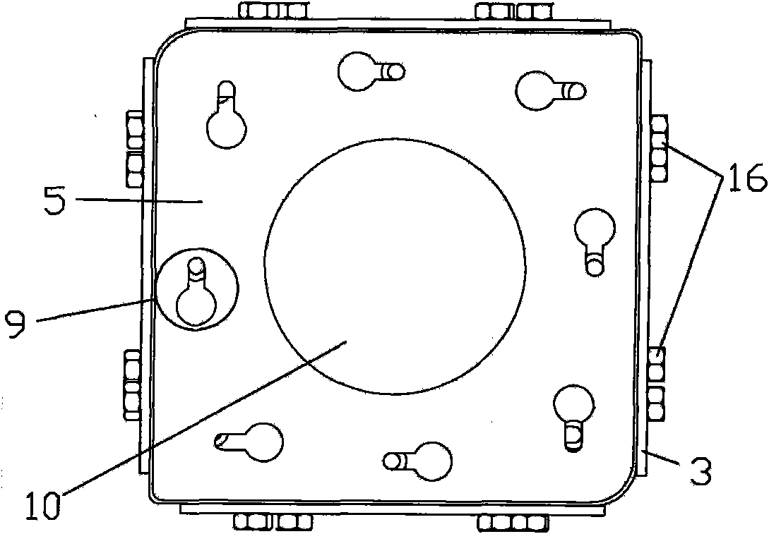
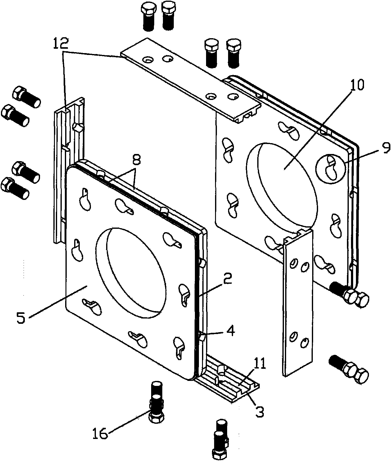
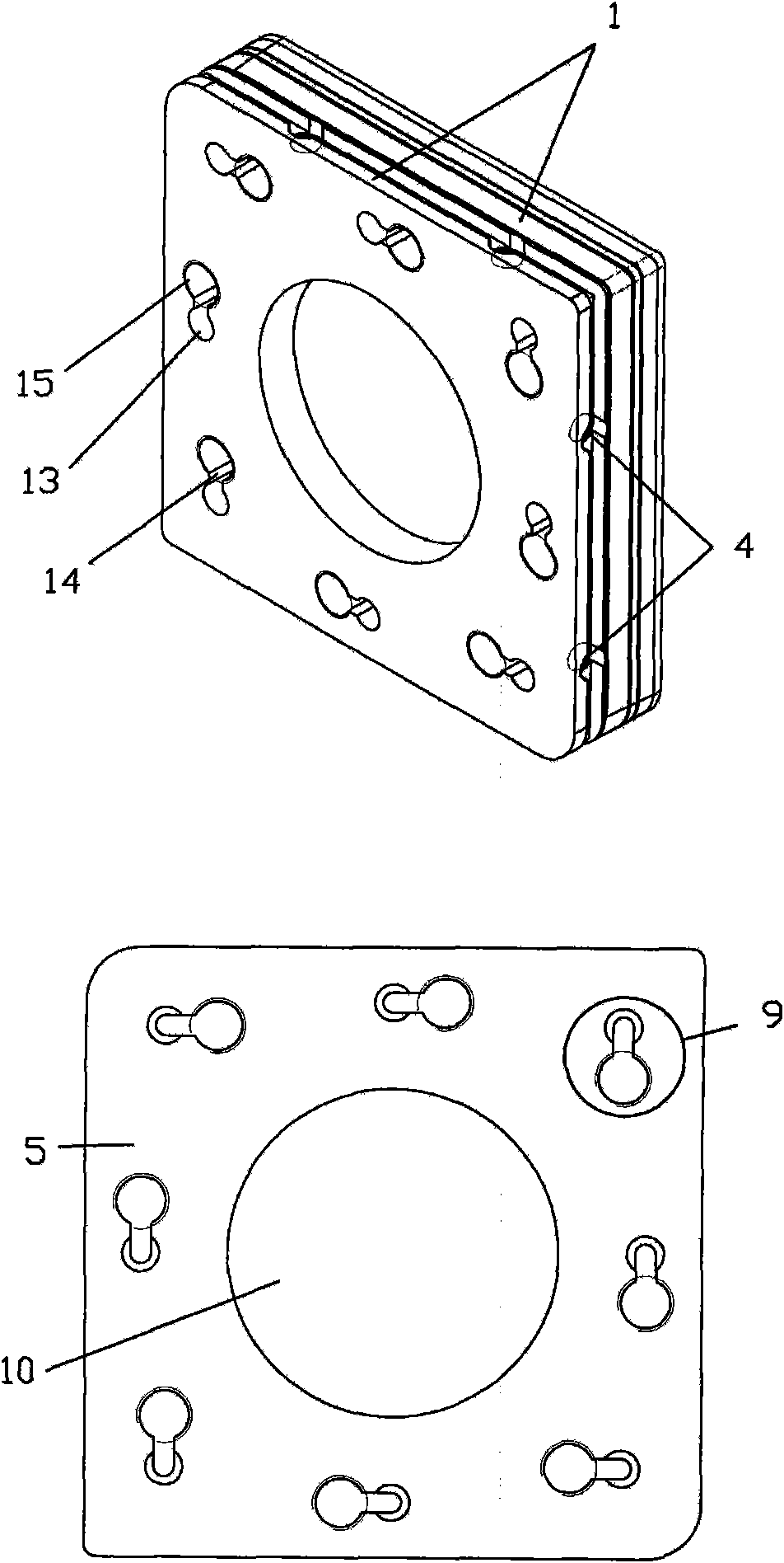
[0025] see Figure 1-Figure 4 , a T-slot mechanical pile connection structure for prefabricated square piles, mainly composed of a prefabricated square pile end plate 1 and a trapezoidal card body 3, when two prefabricated square piles are docked, use the trapezoid on the side of the two prefabricated square pile end plates The groove 2 is engaged with the four trapezoidal clamping bodies 3 connected outside, and then the trapezoidal clamping body and the screw holes 4 at the end plate groove 2 are screwed and connected by bolts 16 to ensure the connection and fixation of the two piles.

[0026] The end plate 1 in this mechanical connection structure consists of a rib plate 5, a clamp mouth 6 provided on the surface of the rib plate 5, a pile ho...


PUM


Abstract

The invention relates to a T-type groove mechanical pile extension structure for a prefabricated square pile, wherein the end part of the prefabricated square column to be butted is provided with an end plate for butting; the structure is characterized in that a groove is arranged on the side surface of the end plate; the side surfaces of the end plates butted with each other are provided with trapezoidal clamp bodies; and the trapezoidal clamp bodies are meshed with the groove on the side surface of the end plate so that the butted end plates are fixedly connected with each other. The pile extension mode of the uplift resisting square pile provided by the invention adopts mechanical connection which can relatively reduce mechanical connections, improve connection reliability, reduce potential safety hazard of foundation engineering and further ensure the safety of buildings.

Description

technical field [0001] The invention relates to a connection structure for prefabricated square pile foundation piles, and is especially suitable for a structural connection of uplift-resistant foundation piles and a specific operation method for this structure. Background technique [0002] With the improvement of the importance of modern buildings and the diversification of structural forms, the requirements for foundation treatment in construction projects have been continuously improved. Most of the supporting and force-transmitting rods are used as permanent pressure-bearing piles, which mainly bear the vertical load. However, there are more and more underground buildings such as underground garages, shopping malls, and pools. The necessary piles commonly used in special occasions such as basements are Pulling piles. In the past few years, many pullout projects used prestressed pipe piles. Due to the disadvantages of unreliable welded joints and other disadvantages, it ...

Claims


Application Information

Patent Timeline
Patent Type & Authority Applications(China)
IPC IPC(8): E02D5/52E02D5/30
Inventor 李红松高军峰张强
Owner SHANGHAI ZHONGJI PILE IND
Learn More