
LED dimming drive system

A technology of dimming drive and LED light bar, applied in the field of control and LED dimming control, can solve the problems of high cost, large volume and high energy consumption, and achieve the effect of low cost and few components

Active Publication Date: 2011-05-18
CHENGDU MONOLITHIC POWER SYST
View PDF5 Cites 11 Cited by
  • Summary
  • Abstract
  • Description
  • Claims
  • Application Information

AI Technical Summary

Problems solved by technology

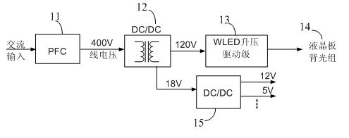
[0004] As can be seen from above, figure 1 The existing LED drive system shown includes multiple converters such as isolated converters, non-isolated converters, and low-voltage converters that provide system power. Each converter needs to be controlled by a controller. Therefore, the circuit components Many, large volume, high cost, and high energy consumption

Method used


Image

  • LED dimming drive system
  • LED dimming drive system
  • LED dimming drive system

Examples


Embodiment Construction

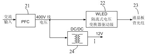
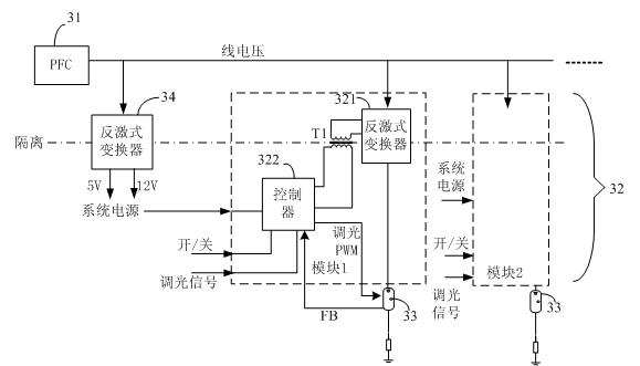
[0016] figure 2 An embodiment of the LED driving system used in the backlight field of the present invention is shown. The LED liquid crystal panel backlight group 23 adopts a two-stage drive system, including a PFC stage 21 and an isolated voltage converter drive stage 22 . The PFC stage 21 rectifies the AC power into a DC line voltage, such as rectifying the AC mains into a DC line voltage of approximately 400V. The isolated voltage converter drive stage 22 converts the line voltage into another DC voltage to provide a stable power supply for the LED backlight group 23 , which does not include a non-isolated boost converter (such as a Boost circuit). The LED liquid crystal panel backlight group 23 is one or more LED light bars. Each light bar is one or more LEDs connected in series. In addition, the drive system also includes a system power converter 24, which converts the line voltage into multiple low-value DC voltages, and provides working power for the isolated volta...


PUM


Abstract

The invention discloses an LED dimming drive system. The drive system comprises a PFC (power factor correction) level and an LED driver level, wherein the LED driver level comprises an isolated converter and a controller. The controller receives a dimming signal to perform dimming on a backlight LED group and controls the output current of the isolated converter at the same time. Through the invention, the control system is simplified, three-level control is simplified into two-level control, the system components are reduced, and the efficiency is improved.

Description

technical field [0001] The invention relates to an LED power supply, in particular to the control of the LED power supply and the dimming control of the LED. Background technique [0002] The white light-emitting diode (LED) light bar group can be used as the backlight of the liquid crystal display (LCD) panel, and can be used in computers, TVs and other occasions, and its application is becoming more and more extensive. [0003] Existing LED backlight power supplies generally use a three-stage drive system, see figure 1 shown. The drive system includes a power factor correction (PFC) stage 11 , an isolated direct current-direct current (DC-DC) voltage converter stage 12 and an LED boost drive stage 13 . The PFC stage 11 rectifies an alternating current such as a 220 volt (V) alternating current mains into a 400V direct current line voltage. The isolated DC-DC converter stage 12 includes an isolated voltage converter, which converts the line voltage into a DC voltage of a...

Claims


Application Information

Patent Timeline
Patent Type & Authority Applications(China)
IPC IPC(8): H05B37/02H05B44/00
CPCH05B33/0848H05B33/0818H05B45/14H05B45/385H05B45/39
Inventor 杜磊刘白仁姚凯威张军明任远程
Owner CHENGDU MONOLITHIC POWER SYST
Learn More