
Transflective fringing field switching type liquid crystal display and manufacturing method thereof

A fringe field switching, liquid crystal display device technology, applied in instruments, nonlinear optics, optics, etc., can solve the problems of difficult processing of resin 10, expensive resin processing, etc.

Active Publication Date: 2012-07-18
CENTURY DISPLAY (SHENZHEN) CO LTD
View PDF0 Cites 0 Cited by
  • Summary
  • Abstract
  • Description
  • Claims
  • Application Information

AI Technical Summary

Problems solved by technology

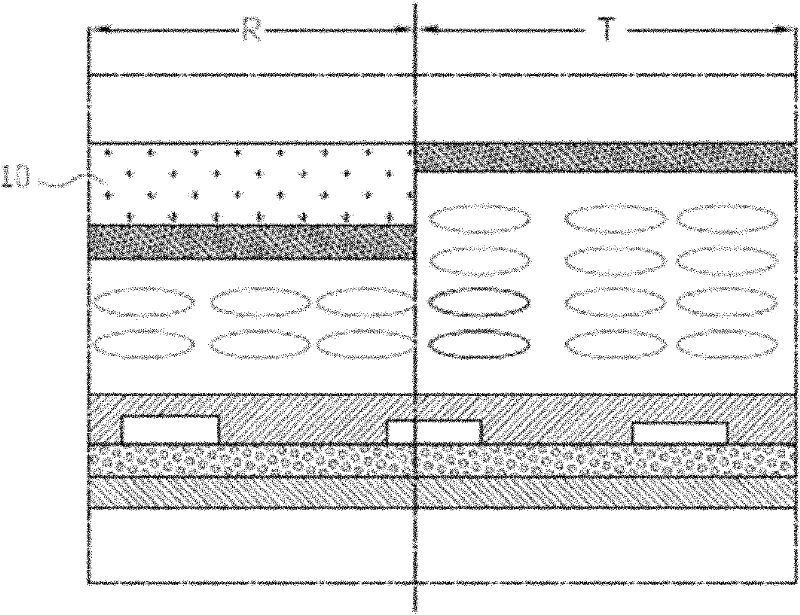
[0006] However, if figure 1 As shown, when the semi-transmissive type is applied to the FFS mode LCD, resin processing (resin process) must be carried out to form concave-convex parts for the reflection area and the transmission area, such as US Patent Publication No. US7414685, which is mentioned in the specification And resin 10 processing is very difficult, this is because basic pollution cannot be completely avoided during its manufacturing process, and this resin processing is also very expensive

Method used


Image

  • Transflective fringing field switching type liquid crystal display and manufacturing method thereof
  • Transflective fringing field switching type liquid crystal display and manufacturing method thereof
  • Transflective fringing field switching type liquid crystal display and manufacturing method thereof

Examples


Embodiment Construction

[0019] The present invention will be described in detail below in conjunction with the accompanying drawings and embodiments.

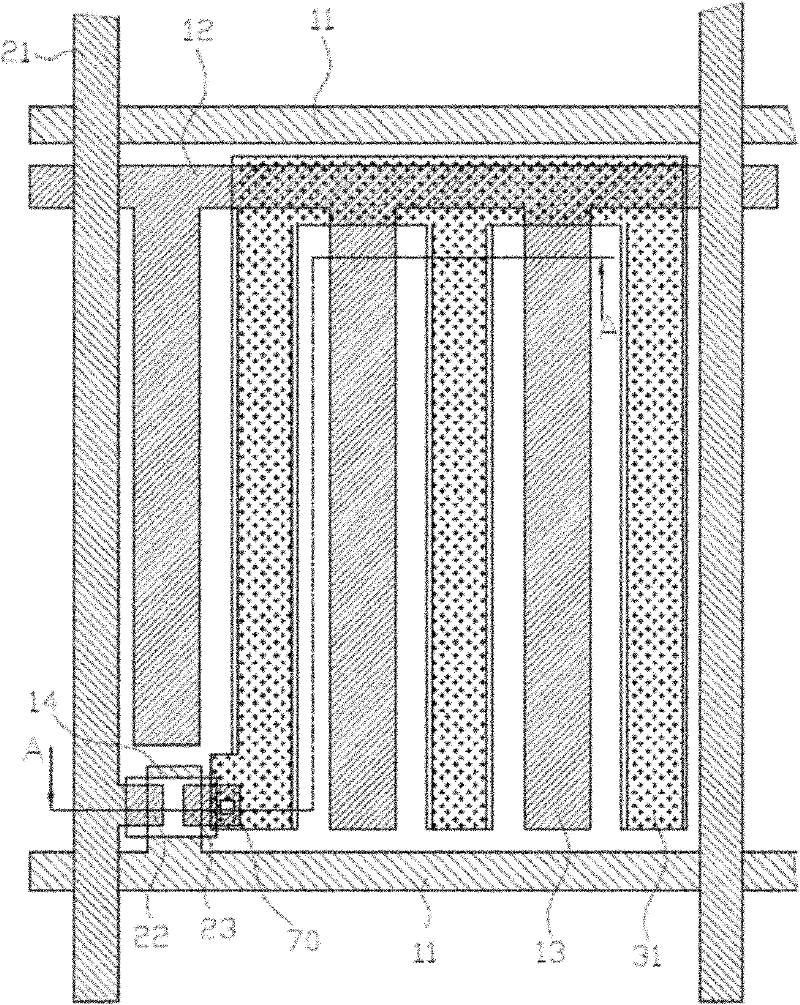
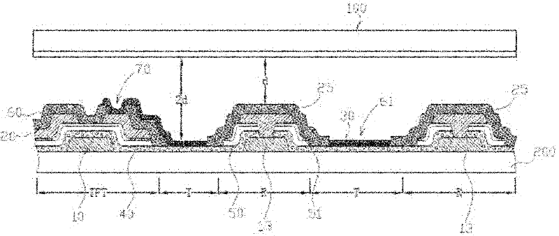
[0020] Please also refer to figure 2 with image 3 shown, where figure 2 It is a schematic diagram of the first embodiment of the FFS transflective liquid crystal display panel of the present invention, image 3 for figure 2 A cross-sectional view along the A-A direction, in the present invention, the pixel display area includes a reflective area R and a penetrating area T, such as image 3 shown, and also refer to figure 2, a first substrate 100, a second substrate 200 and the first substrate 100 are arranged oppositely, a first metal layer 10 is deposited on the second substrate 200, and the first metal layer 10 is formed with scanning lines 11 and common electrode lines 12 , common electrode 13, gate 14, wherein scanning line 11 and common electrode line 12 are arranged along the horizontal direction, common electrode 13 is arranged along ...


PUM


Abstract

The invention provides a transflective fringing field switching type liquid crystal display device which comprises a first substrate and a second substrate, wherein the second substrate comprises a reflection region and a penetration region. The display is manufactured through the traditional illumination manufacture procedure, wherein the space between the penetration region and the first substrate is two times as large as the space between the reflection region and the first substrate.

Description

【Technical field】 [0001] The present invention relates to a semi-transflective fringe field switch (Fringe Field Switch, hereinafter referred to as FFS) type liquid crystal display (Liquid Crystal Display, hereinafter referred to as LCD) and a manufacturing method thereof. The inverted FFS liquid crystal display reduces the manufacturing process time, thereby reducing the manufacturing cost. 【Background technique】 [0002] In the prior art, LCDs can be roughly divided into transmissive LCDs utilizing backlight and reflective LCDs utilizing natural light. Transmissive LCDs use a backlight as a light source, so images can be displayed brightly even in dark environments, but the backlight results in higher power consumption and poor outdoor clarity. Reflective LCDs, on the other hand, use the natural light around them instead of backlighting, so this LCD consumes less power and can be used in outdoor locations, but it cannot be used when the surrounding environment is dark. ...

Claims


Application Information

Patent Timeline
Patent Type & Authority Patents(China)
IPC IPC(8): G02F1/136G02F1/1333
Inventor 黎昔耀江冠贤王明宗
Owner CENTURY DISPLAY (SHENZHEN) CO LTD
Learn More