Floor heating thermostatic valve

A thermostatic valve and floor heating technology, which is applied to valve details, safety valves, balance valves, etc., can solve the problems that the temperature control valve cannot adjust the set temperature value, and cannot apply water and floor heating systems, etc., to achieve a wide range of use and safe operation High, accurate temperature control effect

Inactive Publication Date: 2014-06-11
卓旦春
View PDF1 Cites 0 Cited by
  • Summary
  • Abstract
  • Description
  • Claims
  • Application Information

AI Technical Summary

Problems solved by technology

This temperature control valve should generally be used in high-pressure cleaners. Although it can sense water temperature and generate corresponding actions, it cannot be used in water floor heating systems.
The reasons are as follows: 1. The temperature control valve is opened with the rise of water temperature at the water inlet, while the thermostatic valve in the water floor heating needs to be closed with the rise of water temperature at the water inlet; 2. The temperature control valve cannot Adjust the set temperature value

Method used


Image

  • Floor heating thermostatic valve
  • Floor heating thermostatic valve
  • Floor heating thermostatic valve

Examples


Embodiment 1

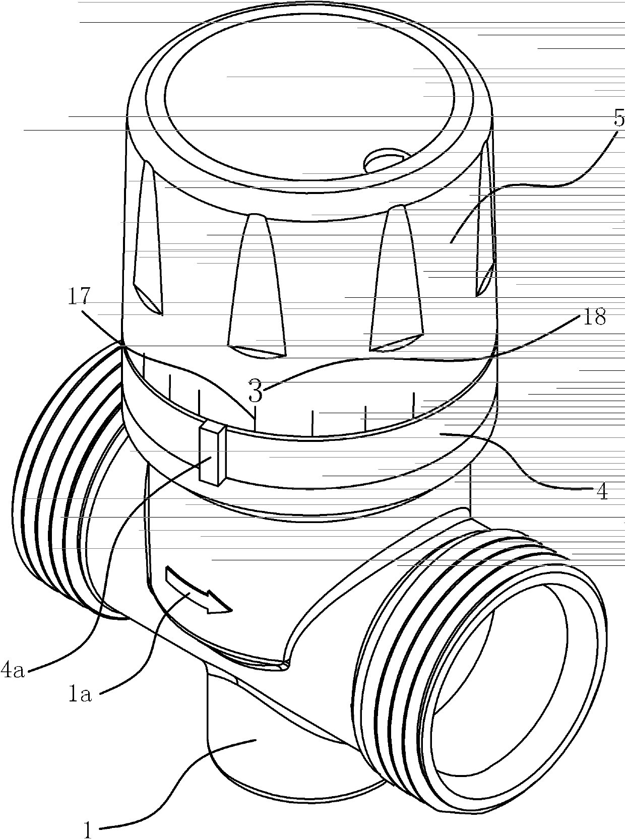
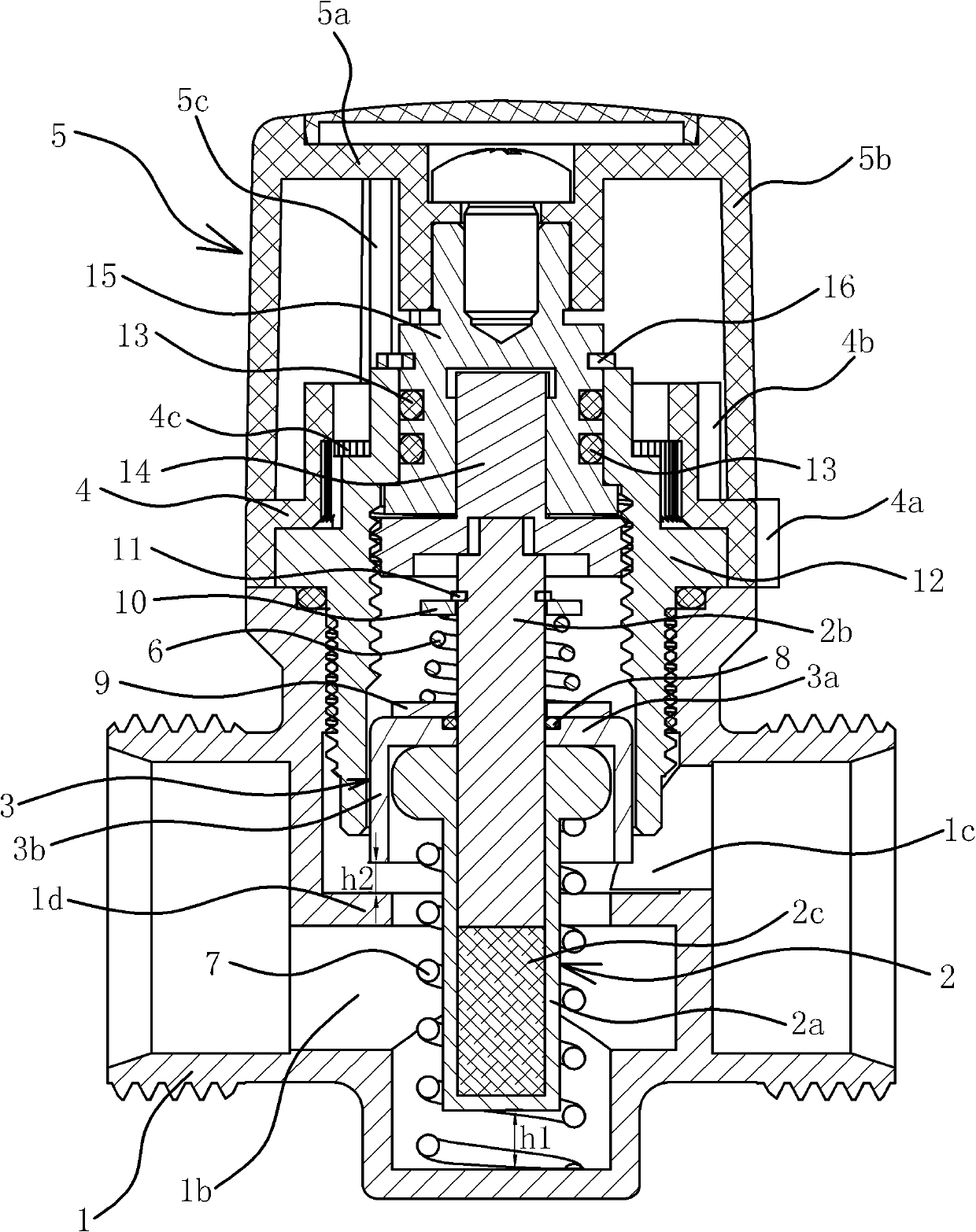
[0036] like Figure 1 to Figure 4 As shown, the local heating thermostatic valve includes a valve body 1, a temperature bulb 2, a valve core 3, a spring one 6, a spring two 7 and an adjustment mechanism.

[0037]Specifically, the valve body 1 has a sealing portion 1d inside, and further divides the inner chamber of the valve body 1 into a water inlet chamber 1b and a water outlet chamber 1c. On the outer wall of the valve body 1 there is an arrow 1a marking the direction of water flow.

[0038] The temperature bulb 2 includes a body 2a, a push rod 2b pierced on the body 2a, and a temperature-sensing medium 2c arranged in the body 2a. The inner end of the push rod 2b can abut against the temperature-sensing medium 2c, and the outer end passes through the body 2a. The temperature bulb 2 belongs to the prior art, and will not be described in detail here. The body 2a of the temperature bulb 2 is located in the water inlet chamber 1b, and the ejector rod 2b penetrates into the w...

Embodiment 2

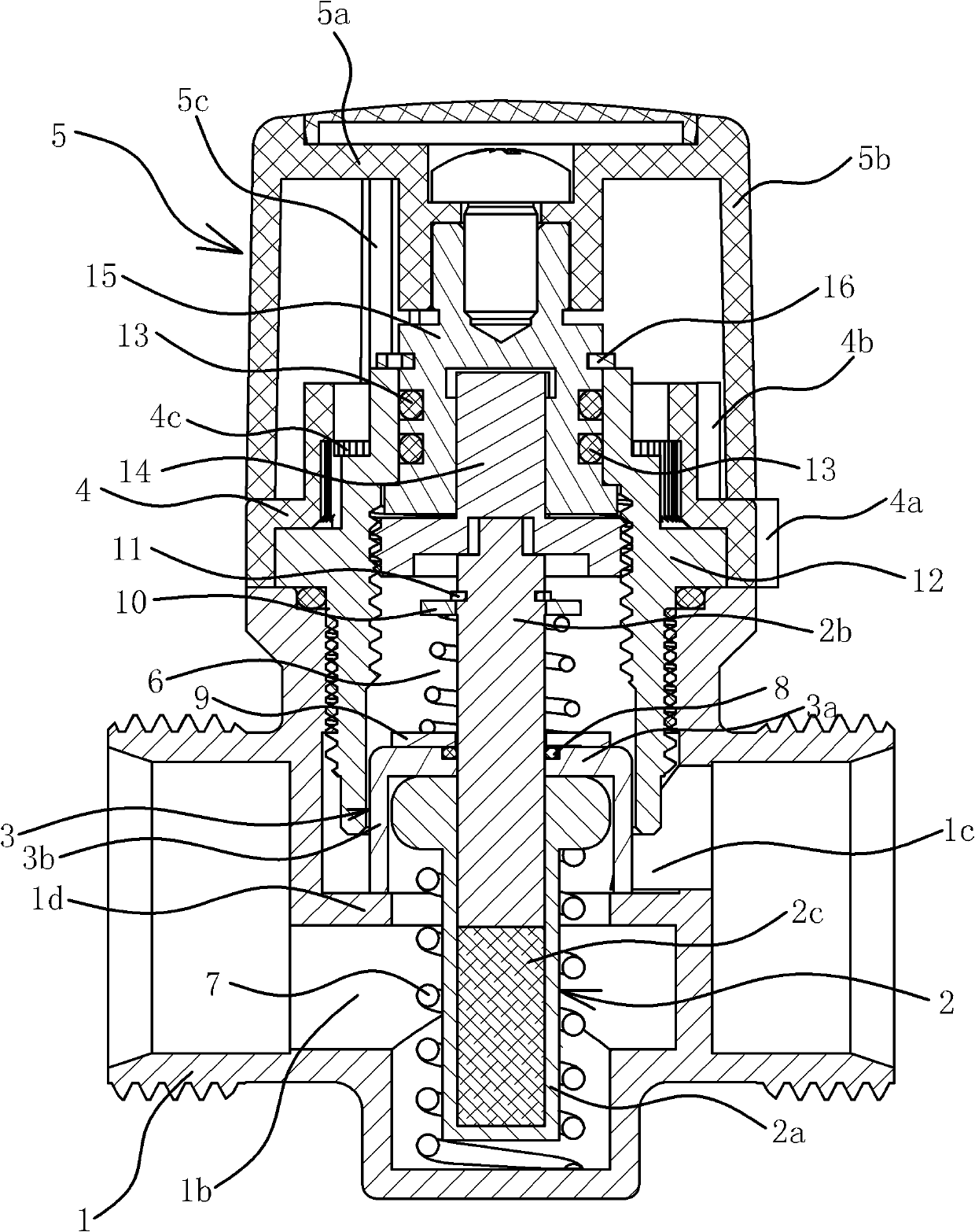
[0055] like Figure 5 As shown, the structure and principle of this embodiment are basically the same as those of Embodiment 1, the difference is that the valve core 3 is located in the water inlet chamber 1b and the valve core 3 is fixedly connected with the outer end of the ejector rod 2b of the temperature bulb 2 . The spool 3 is disc-shaped and connected as a whole with the push rod 2b. A bottom cover 19 is fixedly connected to the side wall of the water inlet chamber 1b of the valve body 1, and a top cover 12 is fixedly connected to the side wall of the water outlet chamber 1c of the valve body 1. One end of the spring one 6 is in contact with the valve core 3, and the other end is in contact with the valve core 3. The top cover 12 leans against each other; one end of the spring 2 7 leans against the body 2 a of the temperature bulb 2 , and the other end leans against the bottom cover 19 .

[0056] The top cover 12 is provided with a lift screw 15 and a lift nut 14, the...


PUM


Abstract

The invention provides a floor heating thermostatic valve, belonging to the technical field of engineering components. The floor heating thermostatic valve solves problems that the traditional temperature control valve opens up only when the water temperature in the water inlet rises and the set temperature value cannot be adjusted. The floor heating thermostatic valve comprises a valve body, wherein the valve body is provided with a sealing part; an inner cavity of the valve body is divided into a water inlet cavity and a water outlet cavity; a temperature bulb and a valve core are arranged in the valve body; the body of the temperature bulb is arranged in the water inlet cavity; an ejector pin of the temperature bulb penetrates into the water outlet cavity; the valve core is hermetically connected with the temperature bulb; a spring 1 is arranged between the valve core and the side wall of the water outlet cavity of the valve body; a spring 2 is arranged between the body of the temperature bulb and the side wall of the water inlet cavity of the valve body; the elastic force of the spring 2 is bigger than that of the spring 1; when the water temperature in the water inlet cavity rises, the valve core moves towards the direction of the sealing part; and when the valve core leans on the sealing part, the body of the temperature bulb moves far away from the direction of the valve core and compresses the spring 2. The floor heating thermostatic valve has the advantages of accuracy and sensitiveness on temperature control, convenience in use and high operation safety.

Description

technical field [0001] The invention belongs to the technical field of engineering components, and relates to a valve, in particular to a floor heating thermostatic valve. Background technique [0002] Floor heating is the abbreviation of radiant floor heating. It uses the whole ground as a radiator, heats the whole ground evenly through the heat medium in the radiant layer of the floor, and uses the heat storage and heat radiation of the ground itself to conduct from bottom to top to achieve The purpose of heating. Compared with traditional heating methods, geothermal radiant heating has many characteristics such as comfort, sanitation, and health care; saving space and beautifying the living room; high efficiency and energy saving; good thermal stability; low operating costs; strong adaptability and long service life. This technology is not only widely used in residential buildings, hospitals, shopping malls and other public buildings, but also in football fields, vegetab...

Claims


Application Information

Patent Timeline
Patent Type & Authority Patents(China)
IPC IPC(8): F16K31/64F16K17/20F16K31/60
Inventor 卓旦春
Owner 卓旦春
Why Eureka
Try Eureka