
Air type position compensation device

A compensation device and air-type technology, which is applied in the direction of fluid pressure actuators, servo motors, mechanical equipment, etc., can solve problems such as hidden dangers in use, front and rear pressure differences affecting service life, etc.

Active Publication Date: 2011-05-18
SHANGHAI MICRO ELECTRONICS EQUIP (GRP) CO LTD +1
View PDF5 Cites 8 Cited by
  • Summary
  • Abstract
  • Description
  • Claims
  • Application Information

AI Technical Summary

Problems solved by technology

In the technical solution provided by the patent, the material of the four airbags is relatively special, which is rubber airbags, and the airbags made of rubber materials are likely to affect the service life due to the large front-to-back pressure difference, especially for some driving devices with large loads. It looks dangerous

Method used


Image

  • Air type position compensation device
  • Air type position compensation device
  • Air type position compensation device

Examples


Embodiment Construction

[0019] In order to make the object, technical solution and advantages of the present invention clearer, the present invention will be further described in detail below in conjunction with the accompanying drawings.

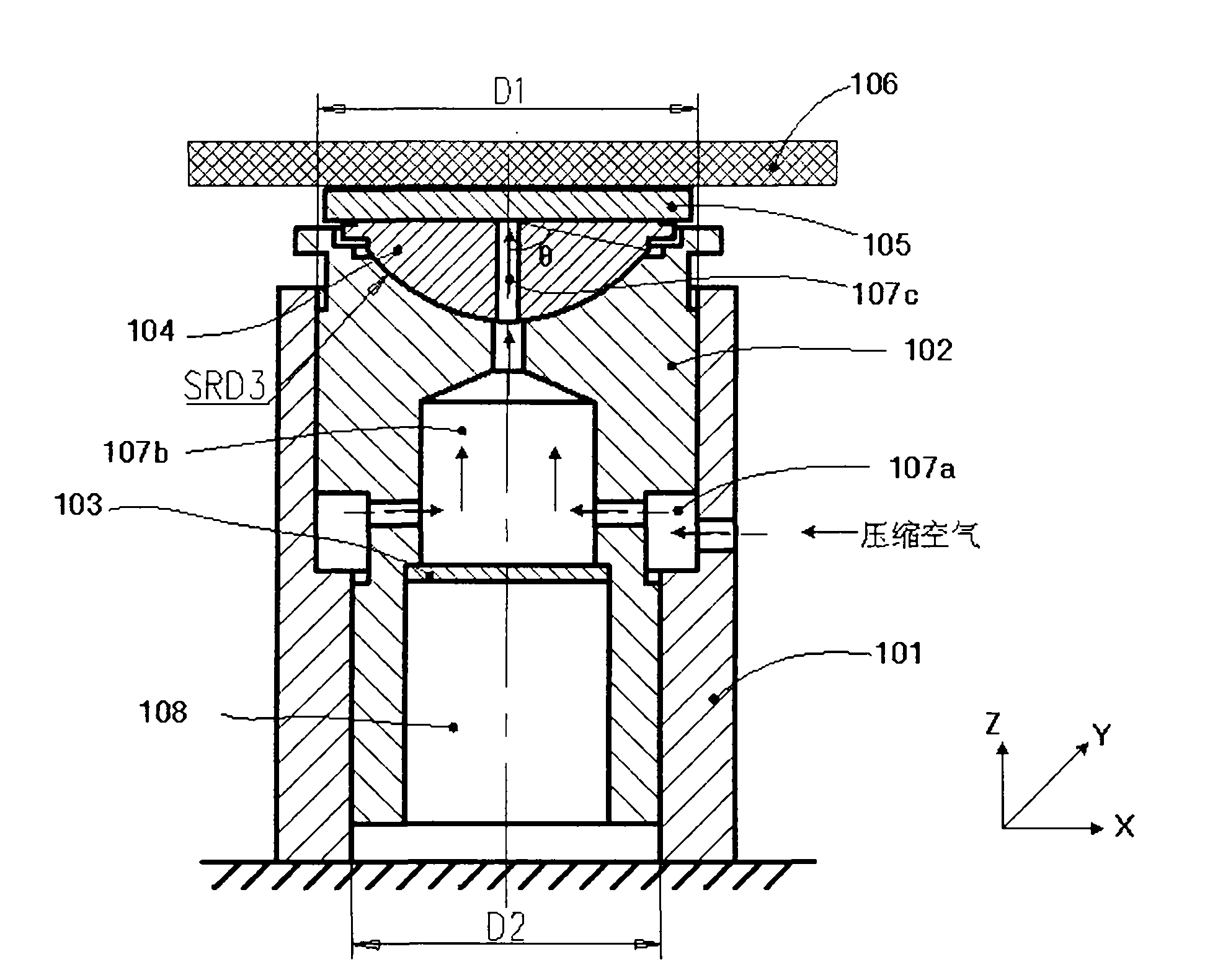
[0020] figure 1 Structural diagram of the air type position compensation device provided by the present invention.

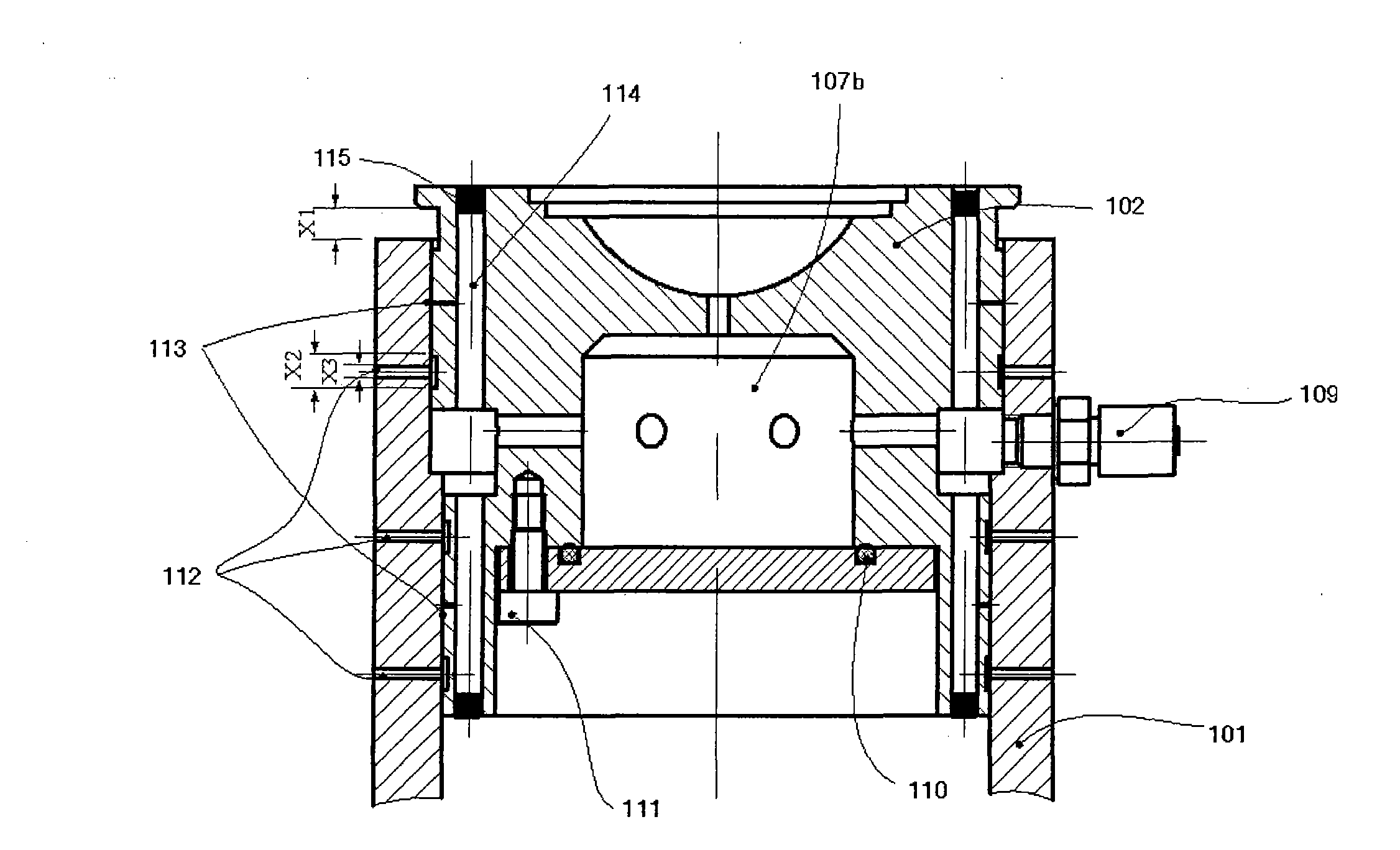
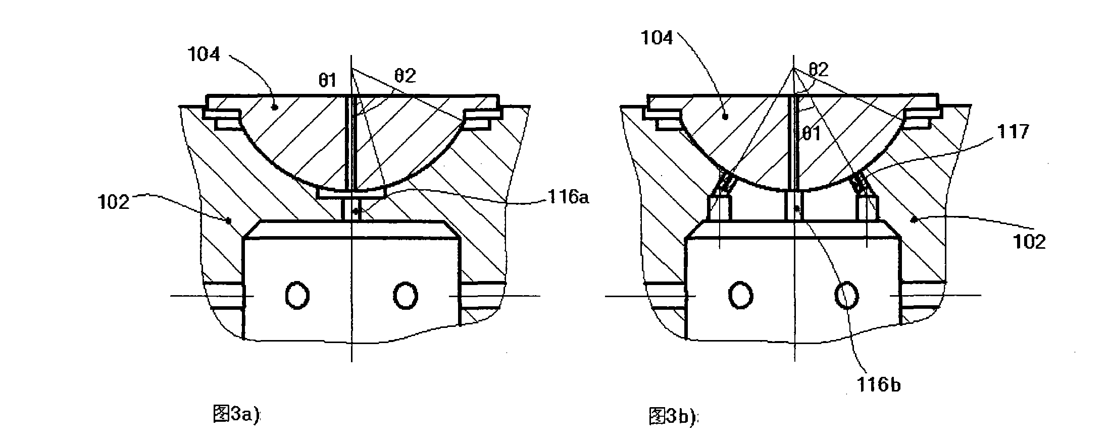
[0021] Such as figure 1 As shown, the air type position compensation device provided by the present invention includes: a base 101 , a variable-section piston 102 , an air chamber seal 103 , a spherical air bearing 104 , a horizontal air bearing 105 and a driving object 106 . Wherein, the variable cross-section piston 102 is located in the base 101 and can move vertically (Z direction). The side wall depression in the middle position between the base 101 and the variable cross-section piston 102 forms a first air chamber 107a, and the inside of the variable cross-section piston 102 There is a second air cavity 107b at the middle and upper end, and...


PUM


Abstract

The invention provides an air type position compensation device and belongs to the field of mechanical equipment. The device has five degrees of freedom and can perform high-precision adjustment on a driven object; the major gravity of the driven object (106) is born by a base (101) and a variable section piston (102) of the device; as the inner medium is air, influence, such as external vibration and the like, can be shielded. In the combined driving of an inbuilt motor of the device, as the major gravity of the driven object (106) is born by the air type position compensation device, the required driving power of a motor is smaller, the heating amount of the motor is low, and the heat stress of the driven object (106) is not influenced, so high speed and high precision position compensation requirement is met.

Description

technical field [0001] The invention relates to a driving device for precision equipment, in particular to an air type position compensation device, which belongs to the field of mechanical equipment. Background technique [0002] With the continuous development of precision equipment and the further reduction of device size, in the driving scheme of precision equipment, it is more and more necessary to adjust the position of the driving object with high precision and multiple degrees of freedom, and the driving device is required to have the ability to shield external vibration. role. In the prior art, a combination of multiple Lorentz motors or a planar motor driving scheme can meet the above-mentioned requirements for driving precision equipment. The amount of heat generated is bound to cause thermal stress deformation and other effects on the driving object. [0003] In this regard, US Patent No. 6,473,161 B2 discloses a position compensator device of the ring motor an...

Claims


Application Information

Patent Timeline
Patent Type & Authority Applications(China)
IPC IPC(8): F15B11/06
Inventor 方洁齐芊枫齐宁宁
Owner SHANGHAI MICRO ELECTRONICS EQUIP (GRP) CO LTD
Learn More