
Molding machine

A molding machine and machine body technology, applied in the field of molding sand molding, can solve the problems of cumbersome adjustment operations, waste of materials, and high height, and achieve the effects of reducing costs, facilitating adjustment operations, and avoiding waste molds

Inactive Publication Date: 2011-05-18
李苏文
View PDF4 Cites 25 Cited by
  • Summary
  • Abstract
  • Description
  • Claims
  • Application Information

AI Technical Summary

Problems solved by technology

However, the position of the pressure plate in the molding machine currently on the market can only be adjusted up and down, and the adjustment operation is relatively cumbersome. Since it is necessary to leave room for operations such as adding sand to the sand box and removing the mold, the pressure plate needs to be set at a higher height. As a result, the height of the traditional molding machine is relatively high, and due to the high pressure of the molding machine when it presses the sand box, a thicker plate is required to make the body, so the height of the molding machine is high, a waste of material and relatively cumbersome

Method used


Image

  • Molding machine
  • Molding machine
  • Molding machine

Examples


Embodiment 1

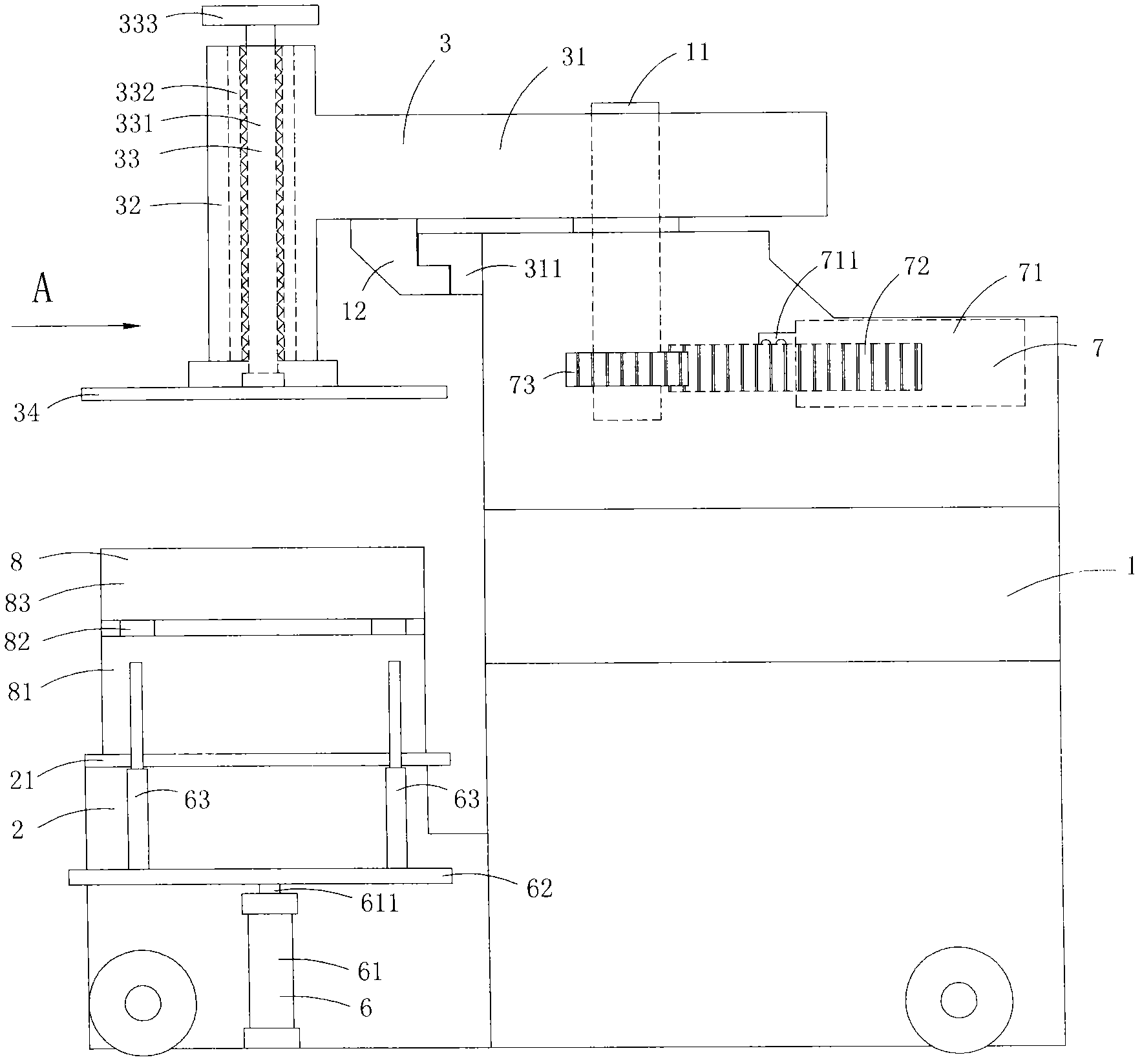
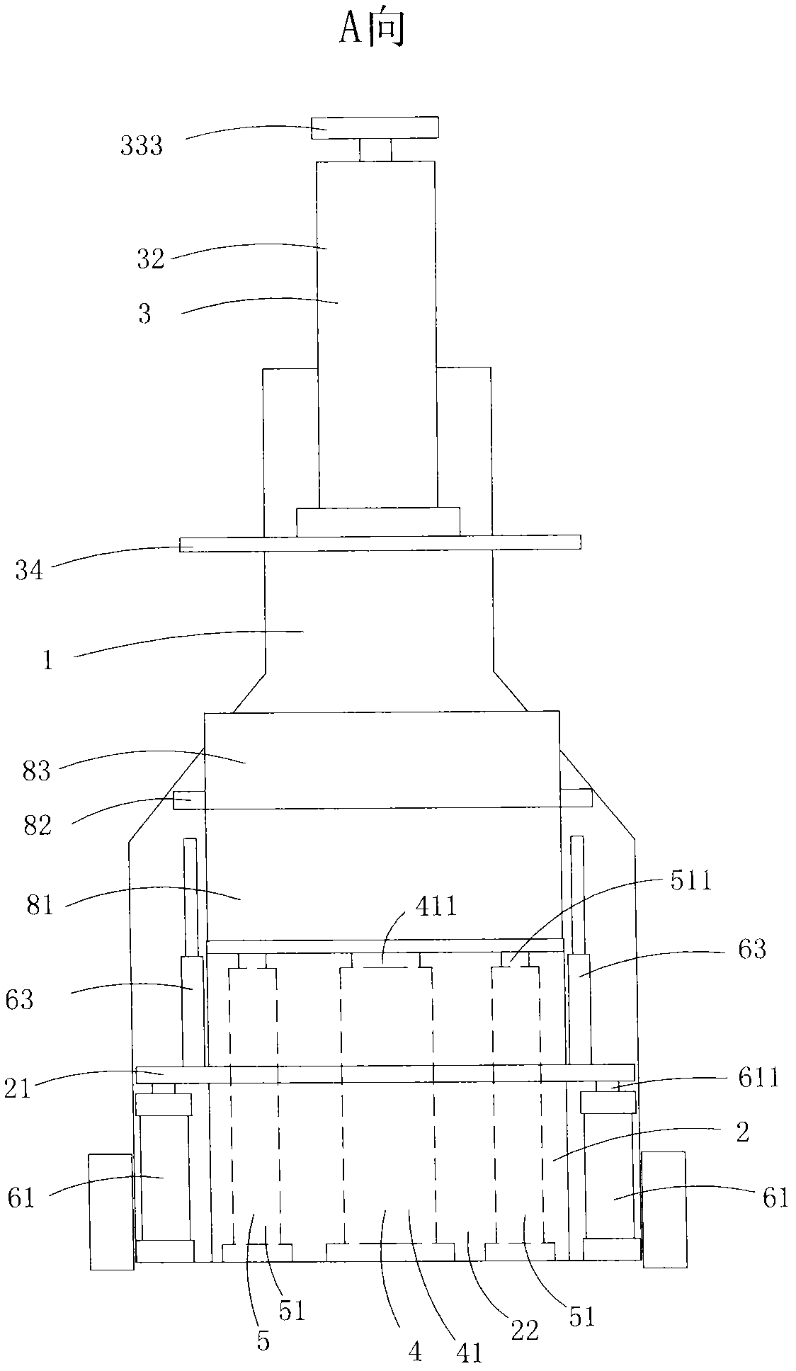
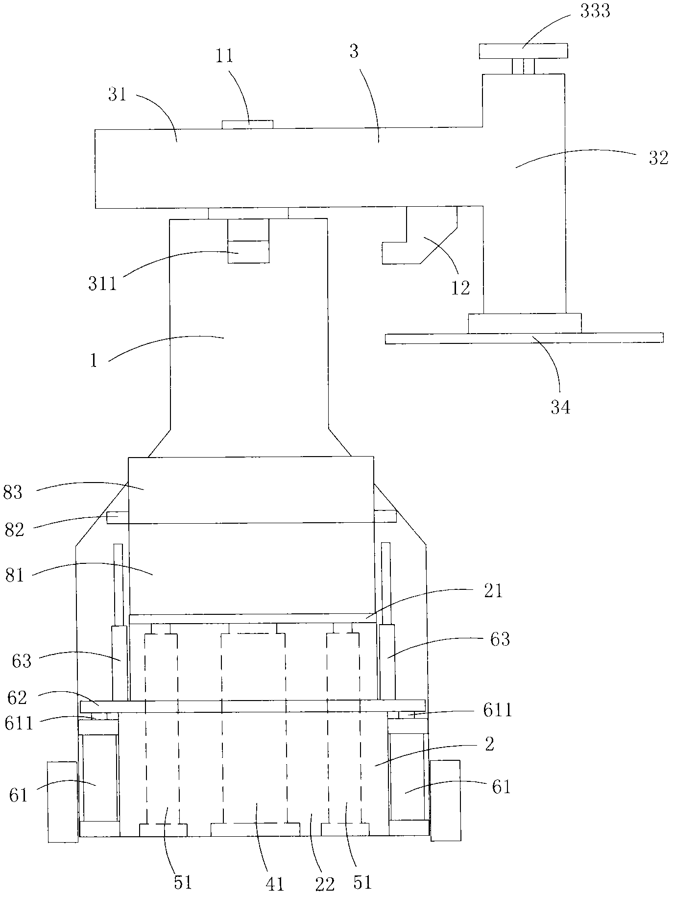
[0026] Figure 1 to Figure 5 A specific embodiment of the invention is shown in which figure 1 It is a schematic diagram of the structure of the invention; figure 2 for figure 1 A-direction view; image 3 for figure 2 A schematic diagram of a state after the rotating rocker arm and the pressing plate in the molding machine shown are rotated 90 degrees; Figure 4 for figure 2 A schematic diagram of the structure of the molding machine shown when the piston of the top pressure cylinder presses the sand box on the working plate to the pressure plate; Figure 5 for figure 2 Shown is a schematic diagram of the structure of the molding machine when the piston of the mold lifting cylinder lifts the upper mold box of the sand box.

[0027] This embodiment is a molding machine, see Figure 1 to Figure 5 , including a body 1, a workbench 2 provided with a working plate 21, a rotating rocker arm 3 provided with a pressing plate 34, a vibrating device 4, a sand pressing device...


PUM


Abstract

The invention discloses a molding machine comprising a machine body, a work table, a rotary rocking arm, a shaking device, a sand press and a mold lifter. The work table is provided with a working plate and is horizontally arranged. The rotary rocking arm is provided with a pressing plate. The top of the machine body is provided with a rotary shaft, and the rotary rocking arm is fixedly arranged on the rotary shaft and can rotate along the rotation of the rotary shaft. The work table is arranged at one lateral end of the machine body, and the rotary rocking arm drives the pressing plate to be arranged just above the work table during the to-and-for rotation. The molding machine enables the pressing plate to horizontally rotate along the rotary rocking arm; when the molding machine adds sands into a sand tank or lifts the mold, the rotary rocking arm and the pressing plate rotate for the certain angle firstly to make the upper part of the sand tank without hampers, therefore, the pressing plate does not need to be arranged at a higher position; and when a jacking compaction operation is carried out, the pressing plate rotates above the work table and the sand tank.

Description

technical field [0001] The invention belongs to the technical field of molding sand molding, and in particular relates to a molding machine. Background technique [0002] The central link of sand casting is molding, and the core of the molding machine is the solid sand mechanism. The compaction molding machine is a low-speed sand-consolidating mechanism that has been used in production for decades. In fact, the sand mechanism is relatively simple, but the compactness of the compacted sand mold is low and the distribution is uneven; the compaction of the forming platen is conducive to improving The uniformity of the compactness of the sand mold at the top of the model and around it; but in general, the compactness of the sand mold obtained by compaction molding is low, especially the compactness of the sand parting surface is low, and the resulting castings have low dimensional accuracy and surface quality. Difference. [0003] With the development of casting production and...

Claims


Application Information

Patent Timeline
IPC IPC(8): B22C15/30
Inventor 李苏文
Owner 李苏文
Learn More