Permanent-magnet multiplied-pole switch reluctance motor

A switched reluctance and motor technology, applied in electrical components, electromechanical devices, etc., can solve the problems of small magnetic energy area, material waste, and little progress in switched reluctance motors, and achieve the effect of power improvement

Inactive Publication Date: 2013-04-24
张世清
View PDF1 Cites 0 Cited by
  • Summary
  • Abstract
  • Description
  • Claims
  • Application Information

AI Technical Summary

Problems solved by technology

[0005] In addition, the switched reluctance motor can only be unilaterally excited during the control of each phase, that is, it can only supply power in one direction and flow in one direction in one switching cycle. For the current, one area in the positive half cycle is used, and the negative half cycle is not used; and although there are two areas within a pole pitch range that can generate torque, only one can be used; and in the process of stator commutation, the number of rotor poles cannot be fully utilized , such as three-phase 6 / 4, each phase can only use 2 poles for the stator, and the rotor can only use 2 poles, and each phase of four-phase 8 / 6 can only use 2 poles for the stator and rotor. Only 4 poles can be used for each rotor, so the magnetic common energy area is small and the material is wasted
At the same time, because the rotor is not a permanent magnet pole, the efficiency of the switched reluctance motor in reversible power generation is very low, only 1 / 3 to 2 / 5
[0006]At present, all countries in the world are researching the new type of motor, the switched reluctance motor, and they all adopt single-chip microcomputer control technology in the control technology, which has made a great breakthrough in its control. And there have been new control-specific module chips, such as DSP chips, but there has been no progress in the switched reluctance motor itself.

Method used


Image

  • Permanent-magnet multiplied-pole switch reluctance motor
  • Permanent-magnet multiplied-pole switch reluctance motor
  • Permanent-magnet multiplied-pole switch reluctance motor

Examples


Embodiment Construction

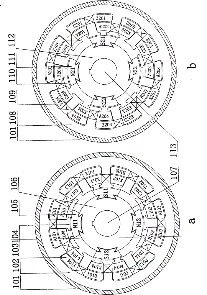
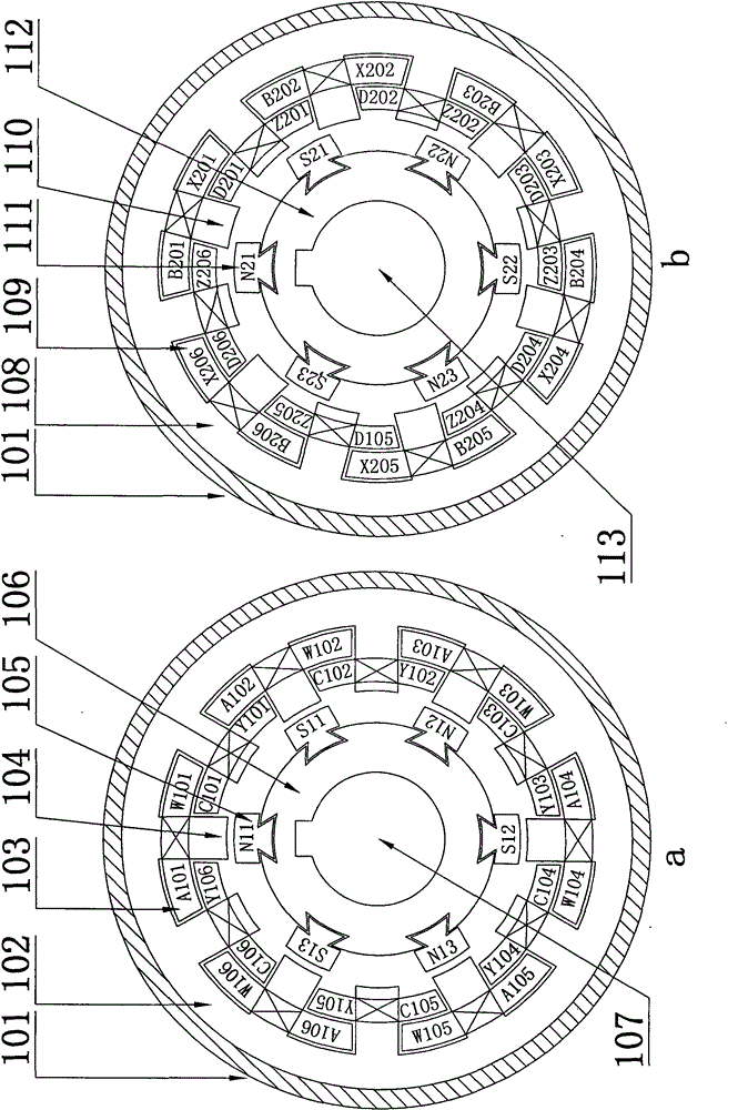
[0047] A permanent magnet multi-pole switched reluctance motor includes a motor casing 101 placed on a motor foot 132 through a motor foot fixing screw hole 131, a motor shaft extension end 118, a motor non-shaft extension end 129, and a built-in motor casing 101. Stator and rotor with doubly salient structure made of laminated silicon steel sheets (see Figure 7 ~ Figure 10 ). The middle part of the motor casing 101 is provided with a motor suspension ring 123; the two ends of the motor shaft extension end 118 are respectively provided with a front end cover 120 and a rear end cover 125, and the front end cover 120 and the rear end cover 125 are connected to the motor casing 101 through a fixing screw 121; The end cover 125 is equipped with a windshield 130, and the windshield 130 is provided with a motor fan 127; a sensor 128 is arranged between the motor fan 127 and the rear end cover 125; the front end cover 120 and the rear end cover 125 pass through the front bearing 119...


PUM


Abstract

The invention relates to a permanent-magnet multiplied-pole generator for a switched reluctance motor. The generator comprises a motor housing, a motor shaft stretching end, a motor shaft non-stretching end, and a stator and a rotor which have double-salient pole structures and are formed by laminating silicon steel sheets, and is characterized in that: a stator core and a rotor core consist of single-segmented two phases or single-segmented three phases; the length and diameter of the stator core are equal to those of the rotor core; a first segment stator core comprises a first segment stator magnet yoke, a first segment stator magnetic pole and first segment stator magnetic pole windings; two sets of centralized or layered first segment stator magnetic pole windings are arranged on thefirst segment stator magnetic pole; armature windings on the two magnetic poles of every set of the winding, which are in the same phase, are connected in series or in parallel to form one phase; andthe first segment rotor core comprises a first segment rotor permanent magnetic pole, a first segment rotor armature magnet yoke, a first segment stator electrically-excited magnetic pole, a first segment stator electrically-excited magnetic pole winding and the shaft hole of the first segment rotor, which is provided with a key groove. The permanent-magnet multiplied-pole generator for the switched reluctance motor is characterized by high efficiency and speed and energy conservation, and has a wide speed regulating range and a wide application range.

Description

technical field [0001] The invention belongs to the field of switched reluctance motors, in particular to a permanent magnet double pole switched reluctance motor. Background technique [0002] At present, the switched reluctance motor is a double-salient switching motor, and its stator poles are wound with concentrated windings; the motor can be divided into three-phase, four-phase and multi-phase switched reluctance motors according to the number of phases. Phase 6 / 4, 12 / 8, and 4-phase 8 / 6 structures are mostly, and the number of stator poles is greater than the number of rotor poles. Switched reluctance motors have simple structure, easy manufacture, easy speed regulation, reliable operation, not easy to damage, and high power factor. , High operating efficiency, large starting torque, small starting current, strong overload capacity, heavy-load starting and other advantages, and at the same time, it has good performance in a wide range of high-speed constant power range....

Claims


Application Information

Patent Timeline
Patent Type & Authority Patents(China)
IPC IPC(8): H02K29/00
Inventor 张世清张红梅
Owner 张世清
Why Eureka
Try Eureka