Eureka AIR delivers breakthrough ideas for toughest innovation challenges, trusted by R&D personnel around the world.

Screw compressor

A screw compressor and compressor rotor technology, applied in mechanical equipment, machines/engines, rotary piston machinery, etc., can solve the problems of unreliable operation of screw compressors and body friction, etc., to eliminate abnormal noise and improve operation reliability effect

Active Publication Date: 2011-05-11
GREE ELECTRIC APPLIANCES INC
View PDF0 Cites 3 Cited by
  • Summary
  • Abstract
  • Description
  • Claims
  • Application Information

AI Technical Summary

Problems solved by technology

[0004] The present invention aims to provide a screw compressor, which can solve the problem that the compressor rotor in the prior art tends to rub against the machine body during the loading process, causing the screw compressor to not operate reliably

Method used


Image

  • Screw compressor
  • Screw compressor
  • Screw compressor

Examples


Embodiment Construction

[0017] The present invention will be described in detail below with reference to the accompanying drawings and in combination with embodiments.

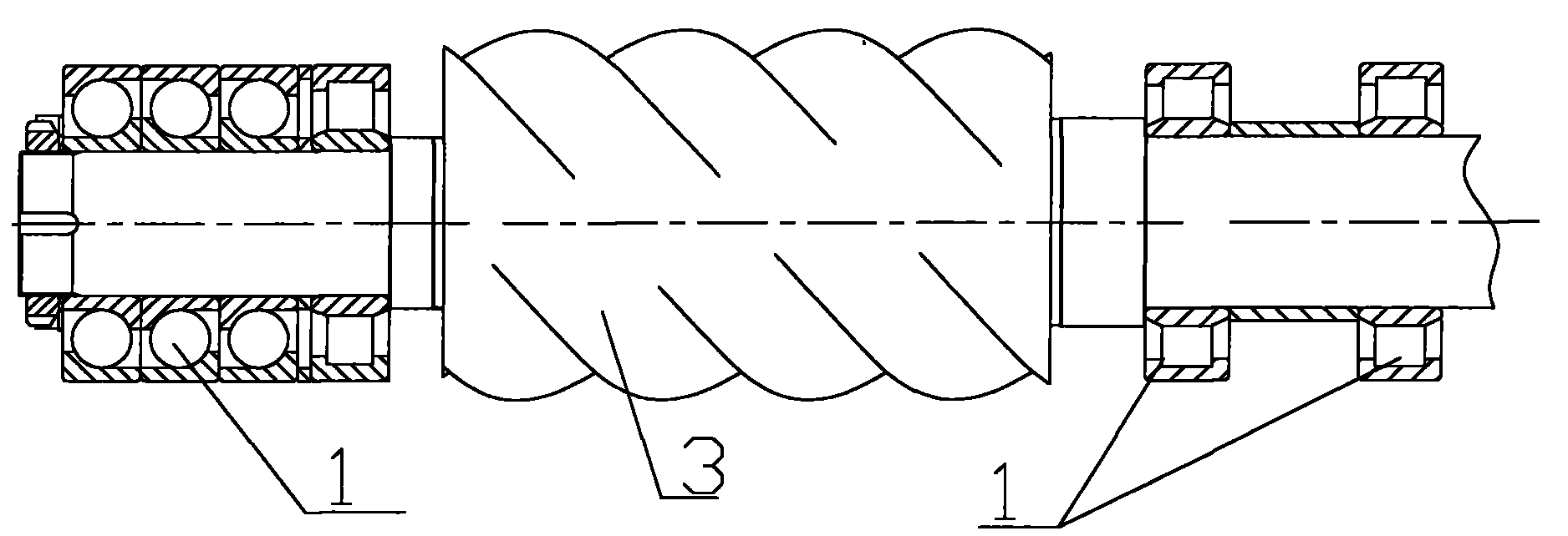
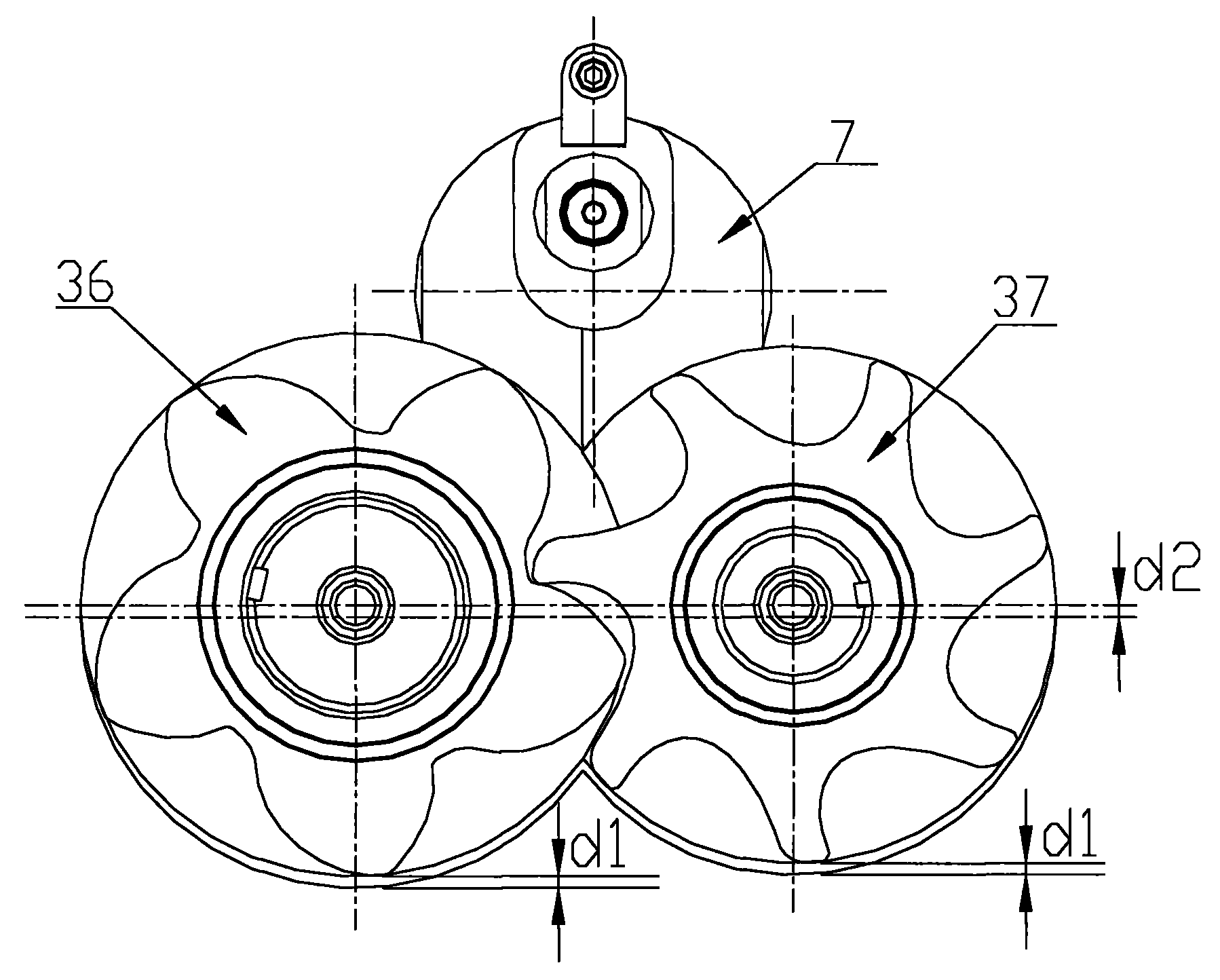
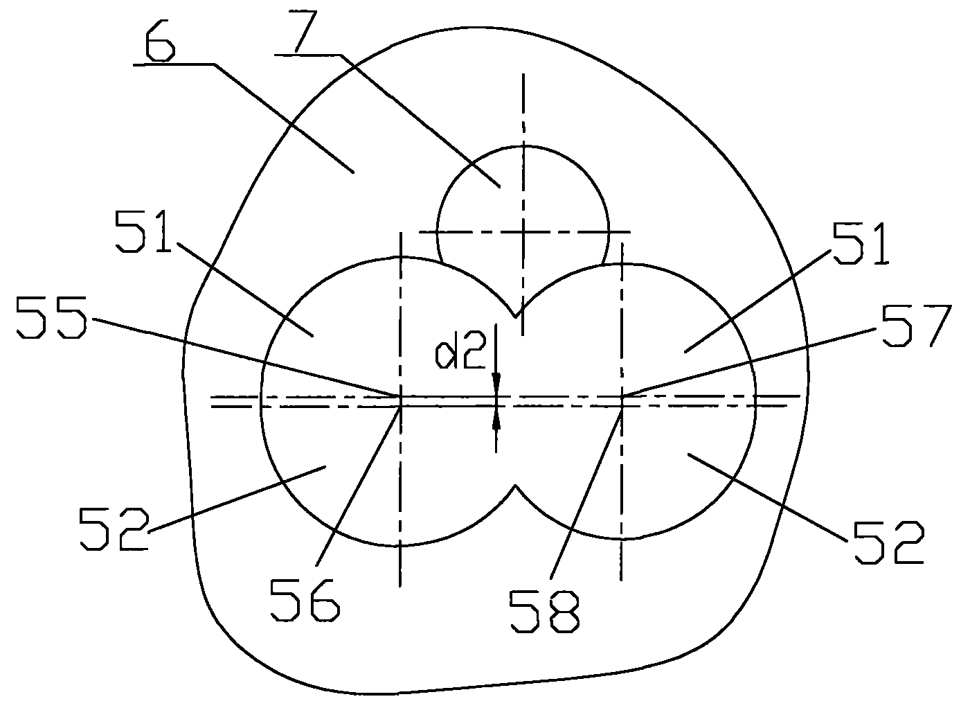
[0018] Figure 1 to Figure 3 Schematically shows the structure of a screw compressor according to an embodiment of the present invention, as shown in the figure, including: a machine body 6; The shaft center of 36 and the shaft center of the female rotor 37 are located on the same horizontal plane; bearing 1; slide valve; body 6 has a slide valve chamber 7 for accommodating the slide valve and a compression chamber for accommodating the compressor rotor 3; the compressor rotor 3 is supported by the bearing Part 1 is supported in the compression chamber; the distance d1 from the lowermost end of the circumscribed circle of the compressor rotor 3 to the lowermost end of the compression chamber is greater than the distance from the uppermost end of the compressor rotor's circumscribed circle to the uppermost end of the compression chamb...


PUM


Abstract

The invention provides a screw compressor, which comprises a body, a compressor rotor, a bearing and a sliding valve. The body is provided with a sliding valve cavity for accommodating the sliding valve and a compression cavity for accommodating the compressor rotor, and the compressor rotor is supported inside the compression cavity by the bearing; and the distance d1 from the lowermost end of the circumscribed circle of the compressor rotor to the lowermost end of the compression cavity is larger than the distance from the uppermost end of the circumscribed circle of the compressor rotor tothe uppermost end of the compression cavity. The inventive screw compressor can effectively prevent the compressor rotor and the body compression cavity from scratching each other during the loading process, eliminates abnormal noise of the compressor, and improves the reliability of the screw compressor.

Description

technical field [0001] The invention relates to the field of air conditioners, in particular to a screw compressor. Background technique [0002] During the capacity loading process of the screw compressor in the prior art, due to the effect of the discharge pressure on the side of the slide valve (the slide valve is generally above the compressor rotor), the radial force of the compressor rotor increases with the effective compression length of the compressor rotor. increase. Both ends of the compressor rotor are supported by bearings (such as radial bearings and angular contact bearings). Due to the bearing clearance, the compressor rotor is longitudinally displaced under the action of the radial force of the compressor rotor. On the contrary, the slide valve On the side, the gap between the compressor rotor and the body will be reduced, which may cause the compressor rotor and the body to be scratched during the loading process of the screw compressor, and the screw comp...

Claims


Application Information

Patent Timeline
Patent Type & Authority Applications(China)
IPC IPC(8): F04C18/16
Inventor 文命清凃星平张天翼周江峰冯顺新李日华
Owner GREE ELECTRIC APPLIANCES INC
Why Eureka
Eureka Blog
Learn More