Pneumatic tire

A technology of pneumatic tires and tires, applied in tire parts, tire tread/tread pattern, transportation and packaging, etc., to achieve high lateral grip and improve rigidity

Active Publication Date: 2011-05-11
SUMITOMO RUBBER IND LTD
View PDF6 Cites 0 Cited by
  • Summary
  • Abstract
  • Description
  • Claims
  • Application Information

AI Technical Summary

Problems solved by technology

[0004] However, in the conventional block pattern, although some improvements have been made in terms of both traction performance and lateral grip performance, there is still room for further improvement.

Method used


Image

  • Pneumatic tire
  • Pneumatic tire
  • Pneumatic tire

Examples


Embodiment

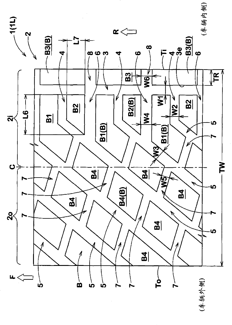
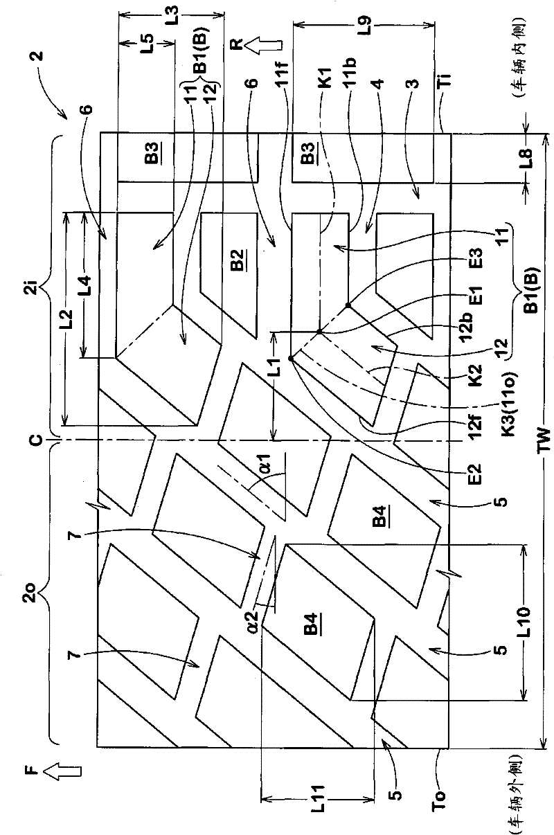
[0074] Pneumatic tires having tread portions having the specifications shown in Table 1 were tested, and their performances were compared. Also, for comparison purposes without having Figure 7 The tread portion of the curved block shown, and having the Figure 8 The same test was carried out on the pneumatic tire in which the shown substantially U-shaped blocks were arranged on the tread portion near the tire equator.

[0075] Tire size: 205 / 60R15

[0076] Rim size: 7J×15

[0077] Tread contact width TW: 190mm

[0078] Inner circumferential groove (groove width W1, groove depth) = (9.0mm, 11.5mm)

[0079] The first transverse groove (groove width W2, groove depth) = (8.0mm, 11.5mm)

[0080] Inclined groove (groove width W3, groove depth) = (10.0mm, 11.5mm)

[0081] Second transverse groove (groove width W4, groove depth) = (10.0mm, 11.5mm)

[0082] Connecting groove (groove width W5, groove depth) = (7.3mm, 11.5mm)

[0083] Inner transverse groove (groove width W6, gr...


PUM


Abstract

The invention provides a pneumatic tire, which can achieve both excellent traction performance and high lateral ground adhesion capability in motor rally or field cross driving. A pneumatic tire comprises a tread portion provided with: an inside circumferential groove near the tread edge; 1st axial grooves extending from the inside circumferential groove toward the tire equator; oblique grooves extending from the respective 1st axial grooves to the outside tread edge, while inclining to the opposite direction to the intended tire rotational direction; 2nd axial grooves extending from the inside circumferential groove to the oblique grooves; and connecting grooves extending between the oblique grooved. The tread portion is provided with bent blocks each made up of an axial part and oblique part. The bent point of the bent block is positioned on the inside tread edge side of the tire equator, and the axial distance therebetween is 0.10 to 0.25 times the tread width.

Description

technical field [0001] The present invention relates to a pneumatic tire capable of achieving a high balance between traction performance and lateral grip performance in off-road running such as rally races and dirt trials. Background technique [0002] For example, the pneumatic tires for running on uneven roads used in off-road driving, especially the tires for racing on uneven roads used in rally races, etc., in order to shorten the driving time, it is also used to firmly grasp the uneven road. The traction performance of the road surface to transmit driving force to the road surface and the lateral grip performance for suppressing lateral slippage of the tires during cornering are very important. Therefore, in order to achieve both traction performance and lateral grip performance, various proposals have been made regarding block patterns such as the shape and arrangement of blocks (see, for example, Patent Document 1 below). [0003] Patent Document 1: Japanese Patent ...

Claims


Application Information

Patent Timeline
Patent Type & Authority Applications(China)
IPC IPC(8): B60C11/03B60C11/117
CPCB60C11/0304B60C19/001B60C2011/0374
Inventor 中野敬太
Owner SUMITOMO RUBBER IND LTD
Why Eureka
Try Eureka