Internal combustion engine and variable inclined-shaft vortex adjusting mechanism

A technology of regulating mechanism and internal combustion engine, applied in the direction of internal combustion piston engine, combustion engine, machine/engine, etc., can solve the problem of inability to adjust the intensity and composition of oblique axis eddy current on demand, complex structure, inability to adjust the intensity and form of gas in the cylinder, etc. problem, to achieve the effect of low cost of modification, low cost and simple structure

Inactive Publication Date: 2011-05-04
MILITARY TRANSPORTATION UNIV PLA
View PDF3 Cites 0 Cited by
  • Summary
  • Abstract
  • Description
  • Claims
  • Application Information

AI Technical Summary

Problems solved by technology

[0011] Schemes 1-4 cannot continuously adjust the intensity and form of the gas macroscopic movement in the cylinder, and belong to the two-state adjustment scheme, and the structure is generally more complicated;
[0012] Although Scheme 5 can continuously adjust the macroscopic motion of the gas in the cylinder to a certain extent, it only has a continuous adjustment function for a single motion - eddy current or tumble flow - and cannot adjust the intensity and composition of the oblique axis vortex motion on demand

Method used


Image

  • Internal combustion engine and variable inclined-shaft vortex adjusting mechanism
  • Internal combustion engine and variable inclined-shaft vortex adjusting mechanism
  • Internal combustion engine and variable inclined-shaft vortex adjusting mechanism

Examples


Embodiment 1

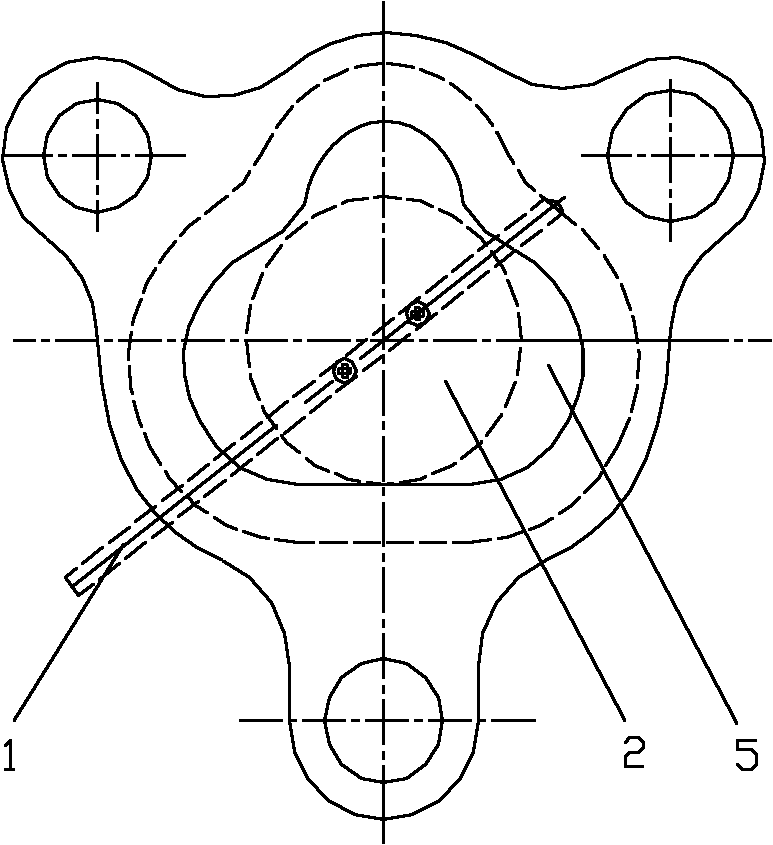
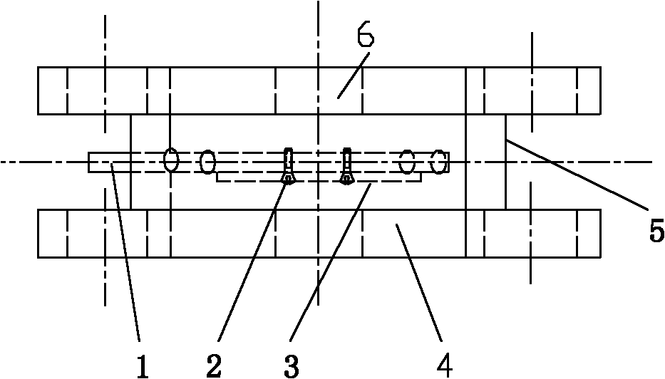
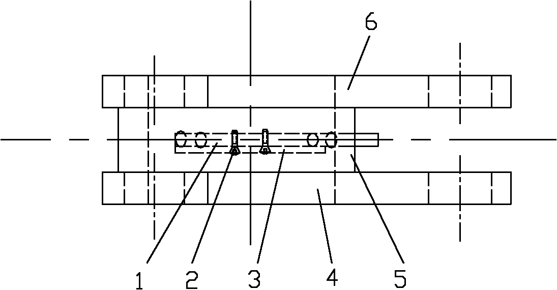
[0034] See attached figure 1 , 2 And 3, the variable oblique axis vortex adjustment mechanism of the present invention is located in the transition pipeline between the intake manifold of the internal combustion engine and the cylinder head inlet, the transition pipeline encloses the transition air passage 5, and the transition pipeline is provided with an oblique axis The swirl control valve plate 3 and its rotating shaft are the inclined-axis vortex control valve shaft 1. The inclined-axis vortex control valve plate 3 is fixed on the inclined-axis vortex control valve shaft 1 through the connecting screw 2. One end of the transition pipeline is connected to the intake manifold. The other end of the connected flange 6 is the flange 4 connected with the cylinder head.

[0035] In the figure, it can be seen that the oblique-axis swirl control valve shaft 1 and the crankshaft axis of the internal combustion engine ( figure 1 There is an inclination angle of 45° between the hor...

Embodiment 2

[0037] This embodiment is a CA4GB four-valve gasoline engine with one-piece gas passage, and the variable oblique-axis swirl adjustment mechanism in Embodiment 1 is provided between the intake manifold and the cylinder head intake passage.

[0038] The variable slant-axis vortex regulating mechanism in Embodiment 1 is used in this engine, and needs to be carried out according to the following steps:

[0039] 1) Design the experimental device comprising the mechanism in Example 1. In the experimental device, the rotation axis of the valve plate must be able to change continuously along the circumference of the transition pipeline.

[0040] 2) On the steady-flow airway test bench, install the experimental device on the engine cylinder head to conduct the airway experiment separately. The α suitable for this engine was found through the steady flow airway experiment v-axis is 60°, so that the adjustment range of the oblique-axis eddy current ratio of the variable inclined-axis ...


PUM


Abstract

The invention discloses an internal combustion engine and a variable inclined-shaft vortex adjusting mechanism. The variable inclined-shaft vortex adjusting mechanism comprises a valve piece positioned between a gas inlet manifold and a cylinder cover gas inlet channel, and a rotary shaft, wherein an inclined angle is formed between the axis of the rotary shaft and the axis of a crankshaft of the internal combustion engine. By utilizing the variable inclined-shaft vortex adjusting mechanism, continuous adjustment can be implemented on the strength and composition of the macroscopic motion of gas in a cylinder of the internal combustion engine and the vortex motion of the inclined shaft, the structure is simple, and the adjustment is convenient.

Description

technical field [0001] The invention relates to the technical field of internal combustion engines, in particular to an internal combustion engine and a variable intake structure thereof. Background technique [0002] The macroscopic movement of gases in the cylinder can be used to improve the combustion process of the engine. In diesel engines, swirl and squeeze motions are usually used to promote fuel atomization and its mixing with air. In gasoline engines, macroscopic movements such as vortex, tumble and squeeze are often used. Their functions include: promoting the formation of mixed gas and increasing the turbulence intensity during combustion. The vortex and tumble motion are organically combined to form an oblique axis vortex. Its main function is to accelerate the combustion in the early stage, stabilize the ignition process, accelerate the subsequent combustion of the entire impulse, and expand the lean burn limit. In addition, the development of stratified lean ...

Claims


Application Information

Patent Timeline
Patent Type & Authority Applications(China)
IPC IPC(8): F02D9/10F02M35/10
CPCY02T10/12
Inventor 刘瑞林赵祥君董素荣许翔刘刚吴晓周广猛
Owner MILITARY TRANSPORTATION UNIV PLA
Why Eureka
Try Eureka