Turning-over method, structure and device for large-scale equipment
A technology of large-scale equipment and equipment, applied in the direction of hoisting devices, etc., can solve the problems of workshop size requirements, harsh requirements, and potential safety hazards.
Inactive Publication Date: 2011-04-27
广州广船国际股份有限公司
View PDF5 Cites 7 Cited by
- Summary
- Abstract
- Description
- Claims
- Application Information
AI Technical Summary
Problems solved by technology
This method requires the preparation of two cranes capable of bearing hundreds of tons of gravity, which is demanding, and it requires a large working space to provide crane operations, and there are requirements for the size of the workshop. Cooperate, there is a security risk
Method used
View moreImage
Smart ImageViewing Examples
Examples
Embodiment Construction
Login to View More PUM
 Abstract
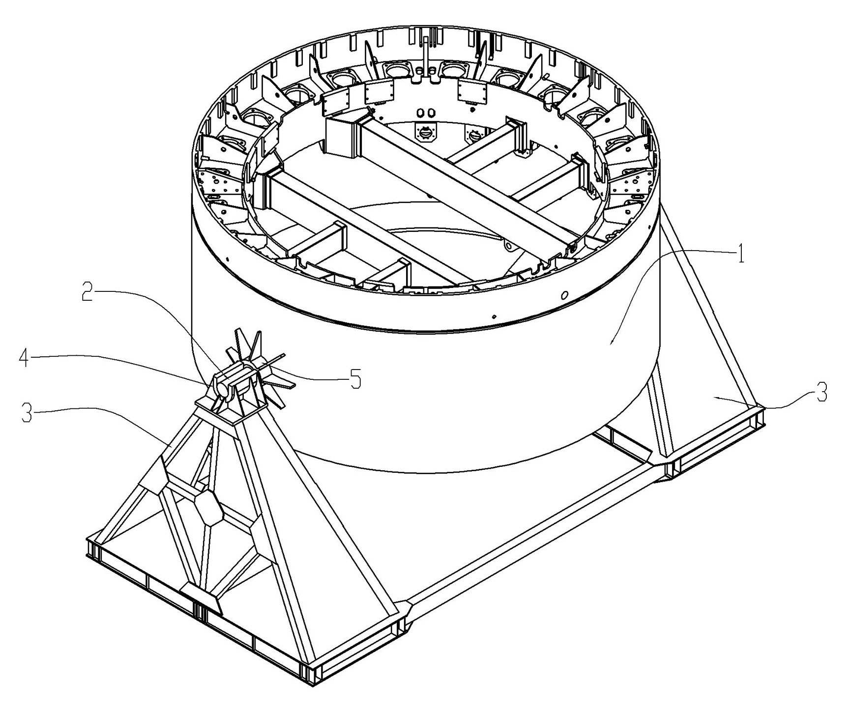
The invention discloses a turning-over method, a turning-over structure and a turning-over device for large-scale equipment. The turning-over structure comprises rotating shafts and the turning-over device, wherein the rotating shafts are arranged on the two sides of the large-scale equipment; the turning-over device is arranged at the bottom of a shield body and is used for supporting the rotating shafts; the turning-over device comprises two supports which are positioned below the rotating shafts on the two sides of the large-scale equipment; U-shaped bases are arranged on the tops of the two supports; the two U-shaped bases are coaxial, are matched with the rotating shafts on the two sides of the large-scale equipment and are used for supporting the two rotating shafts; and the rotating shafts can rotate on the two supports. The large-scale equipment is turned over by the following steps of: placing the rotating shafts on the two sides of the large-scale equipment on the U-shaped bases on the two sides of the turning-over device; lifting one side of the large-scale equipment slightly by using a crane; putting down the large-scale equipment after taking a supporting rod out of the bottom; lifting the other side of the large-scale equipment by using the crane; putting down the large-scale equipment again after taking the supporting rod out, so that the bottom of the equipment is hung in the air, is placed on the U-shaped bases on the two sides of the turning-over device through the rotating shafts on the two sides of the large-scale equipment, and is supported by the two supports of the turning-over device; and rotating the large-scale equipment around the rotating shafts so as to turn over the large-scale equipment. The large-scale equipment is turned over conveniently and quickly.
Description
technical field [0001] The invention relates to a method for turning over large equipment, and a structure and device for turning over large equipment. Background technique [0002] Due to the needs of assembly or work, large-scale equipment sometimes needs to be turned over. However, due to its huge size and weight, turning over is very difficult. Usually, a large crane is required for operation, which not only requires a large operating space, but also takes a long time, and there is a certain degree of danger in the operation. For example, as a shield machine used in the construction of underground tunnels as a large-scale equipment, during the assembly process, many parts (such as: the rings of the shield body, hinged cylinders, propulsion cylinders, etc.) need to be installed in the vertical state of the shield body. For assembly, the shield body is placed in a vertical state, and the bottom is supported by supporting rods. After these devices are installed, the shiel...
Claims
Login to View More Application Information
Patent Timeline
 IPC IPC(8): B66F11/00
Inventor 盛少琴刘德全闫振钟坚杨茨祥洪鹏李金兰郭东刘清煜钱程陈焕杰
Owner 广州广船国际股份有限公司
- R&D Engineer
- R&D Manager
- IP Professional
- Industry Leading Data Capabilities
- Powerful AI technology
- Patent DNA Extraction
Learn More Browse by: Latest US Patents, China's latest patents, Technical Efficacy Thesaurus, Application Domain, Technology Topic, Popular Technical Reports.
© 2024 PatSnap. All rights reserved.Legal|Privacy policy|Modern Slavery Act Transparency Statement|Sitemap|About US| Contact US: help@patsnap.com


