Method and device for resource element mapping

The technology of a mapping device and mapping method, which is applied in the field of resource mapping, can solve problems such as the inability to meet the high processing capacity requirements of the LTE system, and achieve the effect of simplifying logic complexity and high processing capacity

Active Publication Date: 2013-09-11
ZTE CORP
View PDF5 Cites 0 Cited by
  • Summary
  • Abstract
  • Description
  • Claims
  • Application Information

AI Technical Summary

Problems solved by technology

[0009] In view of this, the main purpose of the present invention is to provide a resource element mapping method and device to solve the problem that the existing resource element mapping cannot meet the high processing capability requirements of the LTE system

Method used


Image

  • Method and device for resource element mapping
  • Method and device for resource element mapping
  • Method and device for resource element mapping

Examples


Embodiment Construction

[0032] The technical solutions of the present invention will be further elaborated below in conjunction with the accompanying drawings and specific embodiments.

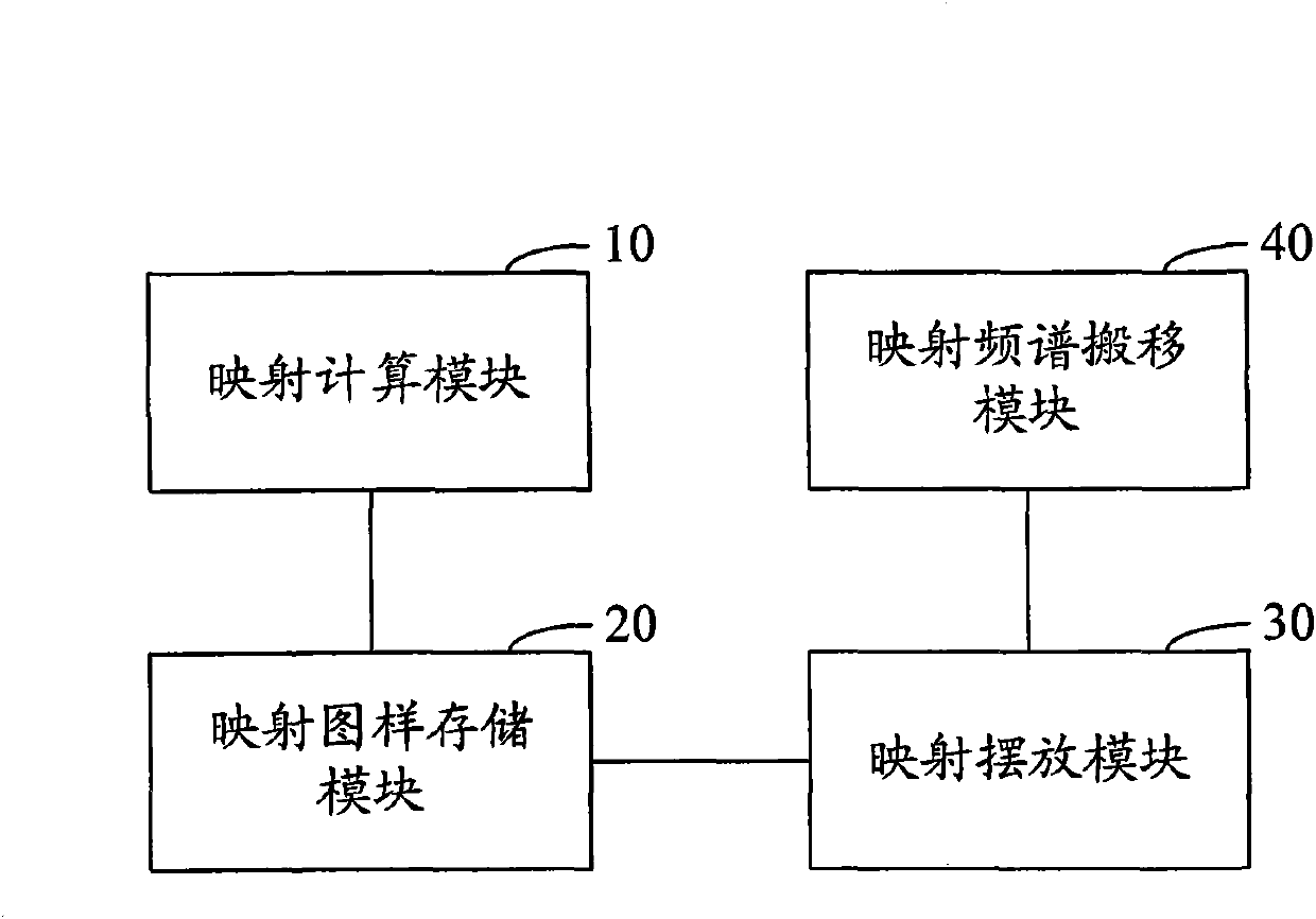
[0033] A resource element mapping device provided by the present invention, such as image 3 As shown, use the hardware description language (HDL, Hardware Description Language) to split the RE mapping into N (N≥2) modules for processing, and each module performs pipeline operations (that is, each module is working at every moment), In order to achieve the purpose of improving system processing capability and simplifying logic complexity.

[0034] image 3 The shown device mainly includes: a mapping calculation module 10 , a mapping pattern storage module 20 and a mapping placement module 30 . The mapping calculation module 10 is used to calculate the signal type that should be placed in each RE of the symbol based on the frame number, subframe number, and symbol number that are two symbols ahead of the system time...


PUM


Abstract

The present invention discloses a device for resource element mapping. The device includes: a mapping computing module, used for computing the signal type which should be placed in each resource element (RE) of the symbol according to the frame-number, the subframe-number and the symbol-number which are ahead of the system time by two symbols when the pulse of every symbol comes, and constituting the RE mapping-pattern; a mapping-pattern storing module, used for storing the RE mapping-pattern computed by the mapping computing module; and a mapping placing module, used for reading the signal type of RE from the RE mapping-pattern stored in the mapping-pattern storing module, and obtaining the modulated and scrambled data from the channel corresponding to the signal type according to the read signal type, when the pulse of every symbol comes. The present invention also discloses a method for resource element mapping. Through the method and device, the requirement of high processing capability of the Long Term Evolution (LTE) system can be satisfied.

Description

technical field [0001] The present invention relates to a resource mapping technology in a long-term evolution (LTE) system, in particular to a resource element (RE) mapping method and device. Background technique [0002] Resource element (RE, Resource Element) mapping refers to the physical downlink shared channel (PDSCH, Physical Downlink Shared Channel), physical downlink control channel (PDCCH, Physical Downlink Control Channel), Physical Broadcast Channel (PBCH, Physical Broadcast Channel), Primary Synchronization Channel (PSCH, Primary Synchronization Channel), Secondary Synchronization Channel (SSCH, Secondary Synchronization Channel), Reference Signal (RS, Reference Signal) and other channels pass through The modulated and scrambled data is placed in the frequency domain and timing positions specified in the 3rd Generation Partnership Project (3GPP, 3Generation Partnership Project) agreement. [0003] The process of LTE downlink physical layer processing, such as ...

Claims


Application Information

Patent Timeline
Patent Type & Authority Patents(China)
IPC IPC(8): H04W48/12H04W72/14H04L27/26
CPCH04W72/1263H04B7/0669
Inventor 闫鹏周刘磊李虎虎贾昊男
Owner ZTE CORP
Why Eureka
Try Eureka