
Stator of an electronically commutated rotor motor

A technology of electronic commutation and electric motors, which is applied in the direction of electric components, electrical components, electromechanical devices, etc., can solve problems such as torque vibration, occupation, and unstable operation of the motor, and achieve the effect of reducing the working current

Active Publication Date: 2015-02-11
ROBERT BOSCH GMBH
View PDF7 Cites 0 Cited by
  • Summary
  • Abstract
  • Description
  • Claims
  • Application Information

AI Technical Summary

Problems solved by technology

The braking torque leads to torque chatter, which makes the motor run jerky, especially for a few revolutions, and which causes the rotor to only assume its rest position in a defined position after the motor has been de-energized

Method used


Image

  • Stator of an electronically commutated rotor motor

Examples


Embodiment Construction

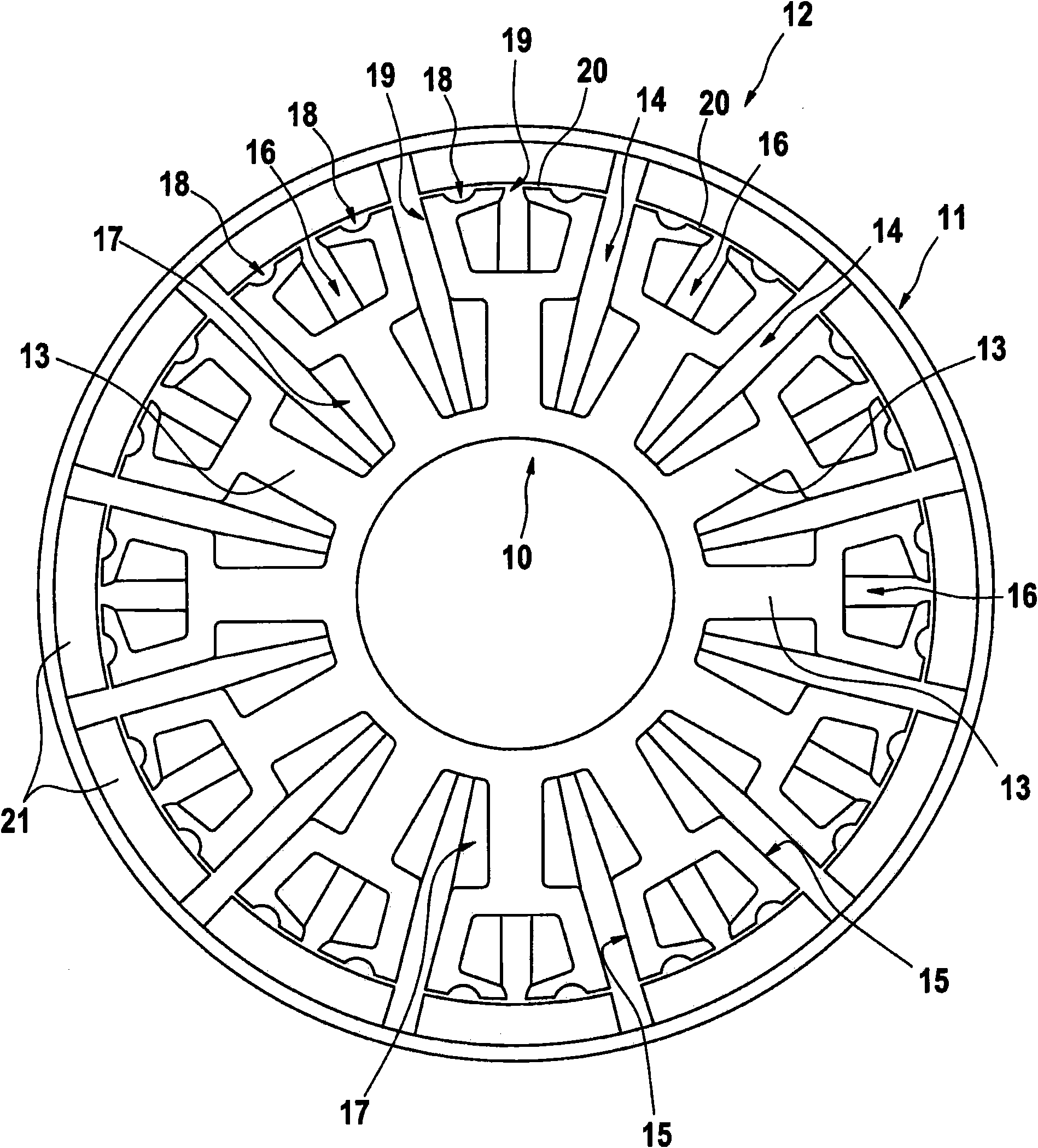
[0017] In this figure, the stator 10 and the rotor 11 of an electronically commutated rotor motor 12 are shown in a sectional view corresponding to the sheet metal section. The stator 10 is provided with a number of poles 13 which are separated from one another by grooves 14, in particular winding spaces. The poles 13 - also called stator teeth - each have a pole fork 15 of the branched type, which is provided with a fork groove 16 . The pole 13 is wound with at least two phase windings 17 , which optionally also surround the pole fork 15 . What is important here is that the pole 13 has at least one additional recess 18 on each pole branch 15 in order to form an additional pole branch 19 . In this way, the air gap 20 that exists between the outer peripheral surface of the stator 10 and the inner peripheral surface of the rotor 11 is partially widened, so as to achieve the corresponding function of the groove 14, more precisely, the function of the bifurcated groove 16 effect...


PUM


Abstract

The invention relates to a stator (10) of an electronically commutated rotor motor (12) having a number of magnetic poles (13) separated by slots (14) and one pole branch (15) each and having at least two winding coils (17) disposed thereon. According to the invention, the magnetic poles (13) on each pole branch (15) have at least one auxiliary slot (18) for forming an auxiliary pole branch (19).

Description

[0001] The invention relates to a stator of an electronically commutated rotor motor with the features indicated in the preamble of claim 1 . Background technique [0002] It is known that electronically commutated rotor motors of the type described generally have a stator combined with a rotor separated by an air gap. The so-called rotor motor refers to a DC motor that runs on DC. Here, the DC motor has a stationary part, the stator, and a rotatably supported part, the rotor. DC motors can be made not only as inner rotor motors, but also as outer rotor motors. In an inner rotor motor, the rotor rotates inside the stator, whereas an outer rotor motor has a rotor that rotates around the stator. [0003] The operating principle of electronically commutated rotor motors (EC-motors) is based on a rotor with permanent magnets and a stator with electronic commutation control. The electronic control unit determines the individual positions of the rotor via sensors, in particular H...

Claims


Application Information

Patent Timeline
Patent Type & Authority Patents(China)
IPC IPC(8): H02K1/16H02K29/03
CPCH02K29/03H02K1/165
Inventor W·克劳特E·H·蒂姆
Owner ROBERT BOSCH GMBH
Learn More