Speed regulating method, speed regulating circuit and lifting device of permanent-magnet motor

A technology of permanent magnet motor and speed regulation method, which is applied in fields such as excitation or armature current control, lifts, transportation and packaging, etc. It can solve problems such as personnel insecurity, large power consumption, and waste of energy, and achieves simple control methods, Save electric energy and achieve the effect of speed control and decrease

Inactive Publication Date: 2011-04-13
白孝林 +2
View PDF10 Cites 0 Cited by
  • Summary
  • Abstract
  • Description
  • Claims
  • Application Information

AI Technical Summary

Problems solved by technology

[0002] Existing lifting devices such as high-rise or super high-rise building elevators, building construction elevators, wharf cranes, and workshop cranes have the following deficiencies: 1. Due to structural limitations, the lifting device must rely on external power supply for both the rising process and the falling process. Power can be provided to work, and it consumes a lot of power, wasting a lot of energy
2. When there is a sudden power failure, because the lifting device does not have the function of continuing to descend, the personnel in the car of the lifting device are in an unsafe state
3. When a fire breaks out in a high-rise building, due to a power outage, the lifting device cannot be reciprocated, and the trapped people cannot implement self-rescue and escape

Method used


Image

  • Speed regulating method, speed regulating circuit and lifting device of permanent-magnet motor
  • Speed regulating method, speed regulating circuit and lifting device of permanent-magnet motor
  • Speed regulating method, speed regulating circuit and lifting device of permanent-magnet motor

Examples


Embodiment Construction

[0033] The present invention will be described in further detail below through specific embodiments and in conjunction with the accompanying drawings.

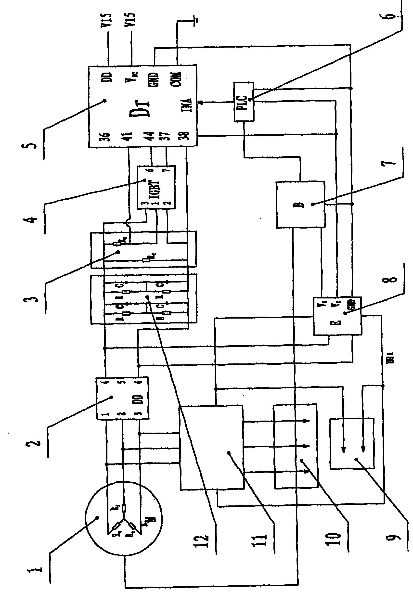
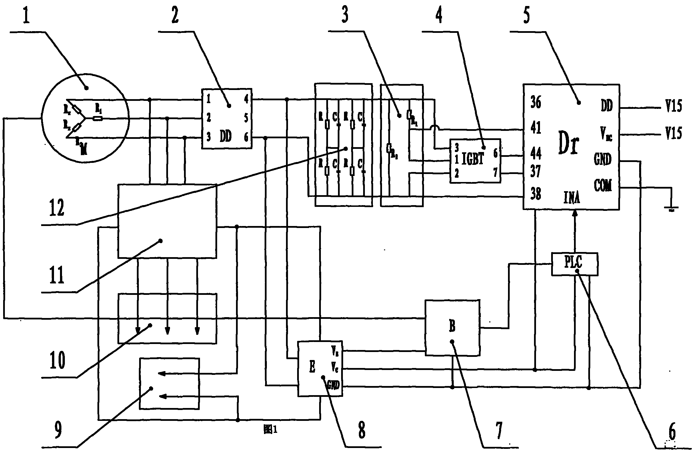
[0034] Such as figure 1 As shown, a speed regulation circuit of a permanent magnet motor, the permanent magnet motor is a permanent magnet motor 2, the speed regulation circuit includes: a winding circuit, the winding circuit includes a permanent magnet motor winding 1, a rectifier bridge 2, a filter circuit 3, a first function Consumption resistor R1, second power consumption resistor R2, insulated gate bipolar transistor (IGBT) 4, driver 5, programmable controller 6, encoder 7, storage battery 8, first interface 9, second interface 10 and inverter 11. The first power dissipation resistor R1 is connected in series with the switch terminal (pin 1 and pin 2) of the IGBT 4 and then connected in parallel with the second power dissipation resistor R2 to form an equivalent adjustable resistance, which is composed of the permanent ...


PUM


Abstract

The invention discloses a speed regulating method of a permanent-magnet motor, comprising the following steps of: serially connecting at least a first power consumption resistor and a high-speed on-off switch device which is controlled by a controlling signal on a winding loop of the permanent-magnet motor; detecting the rotating speed of the permanent-magnet motor; when the rotating speed of the permanent-magnet motor is high, sending the controlling signal to the switch device so that the connection time of the first power consumption resistor in a unit time is long, and the disconnection time is short; when the rotating speed of the permanent-magnet motor is low, enabling the connection time of the first power consumption resistor in the unit time to be short, and the disconnection time to be long; and furthermore, connecting the two ends of both the first power consumption resistor and the high-speed on-off switch device which are serially connected in parallel with at least a second power consumption resistor which is used for limiting the speed. The invention further discloses a speed regulating device and a lifting device of the permanent-magnet motor using the method. By adopting the method, the rotating speed of the permanent-magnet motor of the lifting device is effectively controlled under the circumstance without commercial power supply.

Description

【Technical field】 [0001] The invention relates to a speed regulating method of a permanent magnet motor, a speed regulating circuit and a lifting device. It is especially suitable for permanent magnet motor speed control used in high-rise or super high-rise building elevators, building construction elevators, wharf cranes, workshop driving and group self-rescue and escape equipment when building disasters occur. 【Background technique】 [0002] Existing high-rise or super high-rise building elevators, building construction elevators, wharf cranes, workshop cranes and other lifting devices have the following deficiencies: 1. Due to structural limitations, the lifting device must rely on external power supply no matter in the process of rising or falling. It needs to provide power to work, and it consumes a lot of power, wasting a lot of energy. 2. When there is a sudden power failure, because the lifting device does not have the function of continuing to descend, the personne...

Claims


Application Information

Patent Timeline
Patent Type & Authority Applications(China)
IPC IPC(8): H02P7/06H02P7/28H02P1/22B66B1/30B66B11/02B66B11/04
Inventor 白孝林朱清明傅涛
Owner 白孝林
Why Eureka
Try Eureka