Veneer power-up device

A technology for electrical devices and single boards, which is applied to coupling devices, measuring devices, and components of connecting devices, etc., can solve problems such as power-on and power-off testing of single boards, power failure of single boards, and inconvenient disassembly and assembly. , to achieve the effect of stable and reliable working power, convenient installation and disassembly, and exquisite structure

Active Publication Date: 2013-11-06
南通中南智能科技有限公司
View PDF5 Cites 0 Cited by
  • Summary
  • Abstract
  • Description
  • Claims
  • Application Information

AI Technical Summary

Problems solved by technology

The above-mentioned elastic connection method is relatively reliable without moving the board, but if the board is moved frequently, the charging rod will move with the board, and it is easy to cause the hook of the power-up hook to detach from the board. The power-on shrapnel of the board, so that the board is powered off
[0006] 2. It is easy to cause short circuit
figure 1 As shown in the energization hook, the small hook is a completely bare metal part. During the process of moving the board, it is easy for the small hooks on the two energization rods to cross each other and cause a short circuit; or, the shrapnel between the small hook and the energization shrapnel short circuit caused by touching
[0007] 3. Inconvenient disassembly and assembly
During the board debugging process, the opening of the power-on shrapnel on the board is small, and it is not convenient to extend and insert the small hook on the power-on rod
[0008] 4. It is easy to deform the shrapnel when it is powered on
[0009] Therefore, the existing power-on device is no longer suitable for the power-on and power-off test of the single board, and a power-on device more suitable for the single board debugging process is needed

Method used


Image

  • Veneer power-up device
  • Veneer power-up device
  • Veneer power-up device

Examples


Embodiment Construction
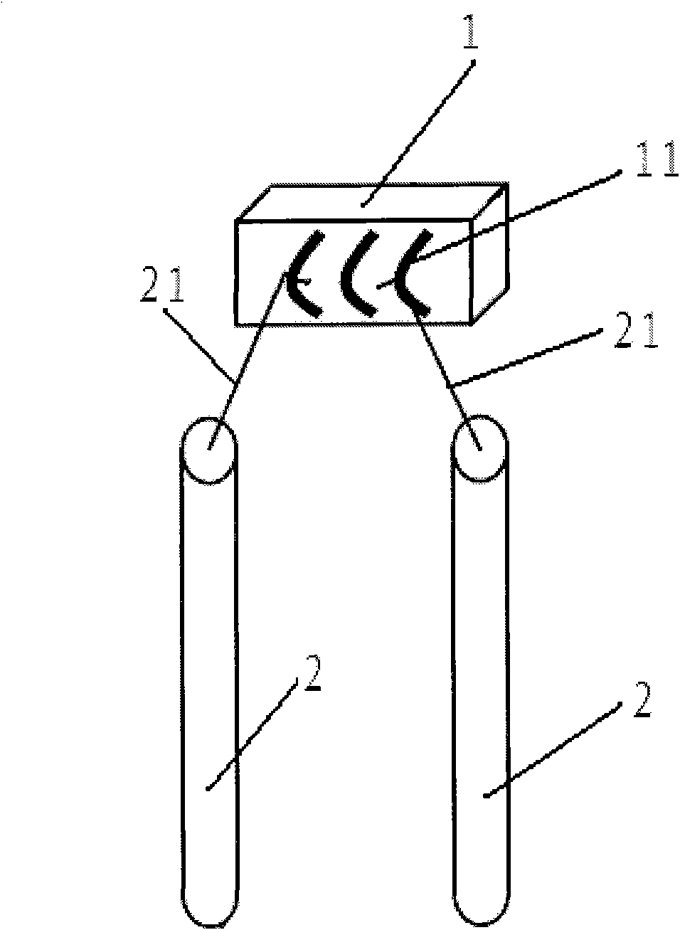
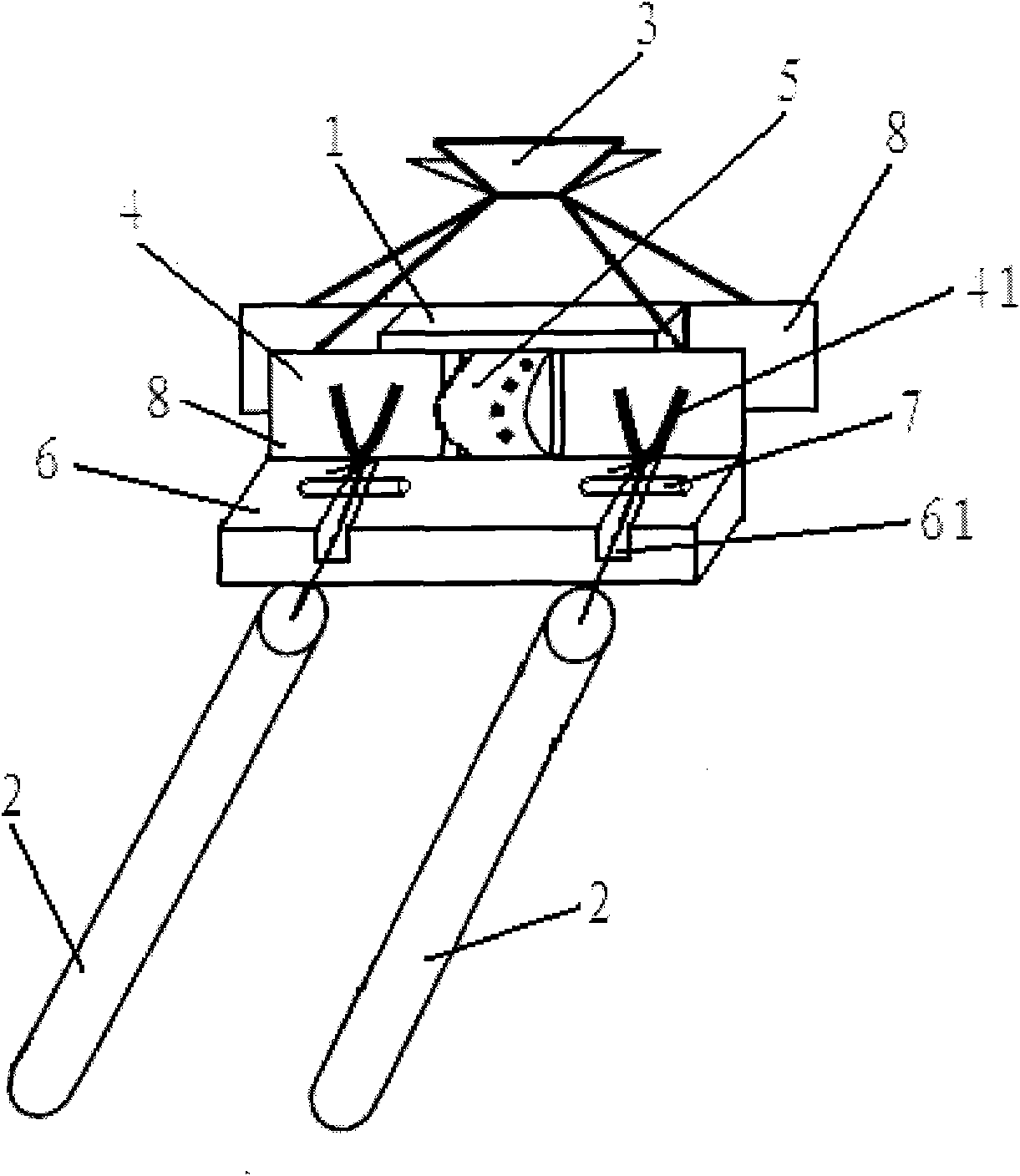
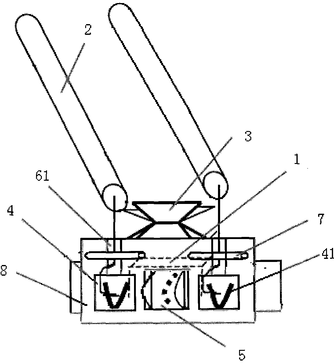
[0022] The basic idea of ​​the present invention is that, by setting the power supply device of the single board as a clip structure, and setting the connecting piece and the conductive sheet on the clamp plate of the While working on the power supply, it is also convenient to disassemble the board. That is, as long as the two splints of the clip clamp the veneer, and then connect the charging rod with the hook and loop on the conductive sheet set on the splint, the veneer can be supplied with working power. Furthermore, by providing a groove for placing the hook telescopic wire and a small rod for holding the hook telescopic wire, the connection between the power rod and the power shrapnel of the single board is also relatively stable.

[0023] In order to make the object, technical solution and advantages of the present invention clearer, the present invention will be further described in detail by citing the following embodiments and referring to the accompanying drawings. ...


PUM


Abstract

A single-board power-on device includes power-on rods (2) provided with extensible hooks. Power-on spring contacts serving as connection points for the single-board power supply are provided on the single-board. The device also includes a clip which clamps and holds the single-board. Conducting strips (4) are provided on one arm of the clip. The conducting strips (4) are provided with hook-rings on an outer face of the arm, said hook-rings being connectable with the hooks. The conducting strips (4) are further provided with connection elements on the inner face of the arm, said connection elements being in connectable contact with the power-on spring contacts. The device can supply a stable and reliable working power source for the single-board and is easy to disassemble and assemble.

Description

technical field [0001] The invention relates to a single board power supply technology, in particular to a single board power supply device. Background technique [0002] In the field of electronic equipment manufacturing, the manufacture of single boards is particularly important. The single board is an indispensable part of electronic equipment and the heart of realizing the functions of electronic equipment. During the board manufacturing process, debugging is the top priority. Among them, during the mid-term debugging of the single board, it is necessary to power on and off the single board from time to time, so as to cooperate with the completion of the single board test and component welding. [0003] figure 1 It is a schematic diagram of the structure of the existing single-board power supply device. At present, the general structure of the single-board power supply device is as follows: figure 1 As shown, the power-on device is mainly composed of a power-on rod 2 ...

Claims


Application Information

Patent Timeline
Patent Type & Authority Patents(China)
IPC IPC(8): H01R4/48H01R4/58H01R13/02H01R13/502H01R13/72
CPCH01R4/48G01R31/02H01R13/02H01R4/58H01R13/72H01R13/502G01R31/52
Inventor 杨正淼
Owner 南通中南智能科技有限公司
Why Eureka
Try Eureka