
Single-machine polarizing stereo film imaging system and imaging method

A technology of stereoscopic film and imaging system, applied in stereoscopic photography, optics, photography, etc., can solve the problems of rising cost, poor definition, inability to promote, etc., and achieve simple operation steps, reduced hardware cost, and reduced visual acuity. effect of fatigue

Active Publication Date: 2011-04-13
SHINING 3D TECH CO LTD
View PDF8 Cites 3 Cited by
  • Summary
  • Abstract
  • Description
  • Claims
  • Application Information

AI Technical Summary

Problems solved by technology

(4) Grating type, this method can make the received TV programs three-dimensional. my country has now produced a grating type stereo TV set, but the grating type also has disadvantages, that is, the definition is worse than other three-dimensional ones. Only slightly higher definition on very large TVs, which also drives up the cost significantly
(7) Holographic type, which cannot be promoted at present
The disadvantage is: because the screen area is reduced by half, the amount of information and luminous flux of the fixed screen is also reduced
The disadvantage of dual-machine polarized stereoscopic film is that the shooting and projection cannot fully synchronize the two machines

Method used


Image

  • Single-machine polarizing stereo film imaging system and imaging method
  • Single-machine polarizing stereo film imaging system and imaging method
  • Single-machine polarizing stereo film imaging system and imaging method

Examples


Embodiment Construction

[0020] Below in conjunction with accompanying drawing and embodiment, the present invention will be further described:

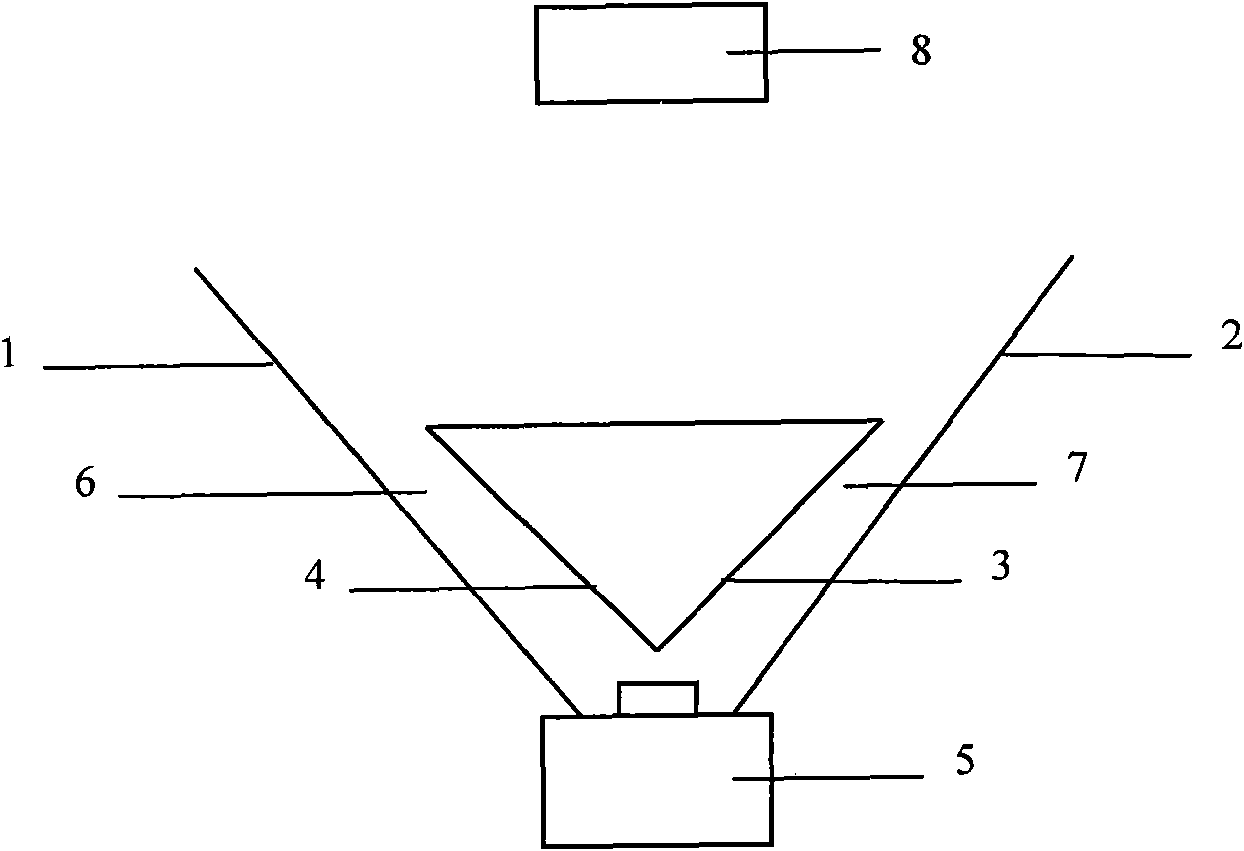
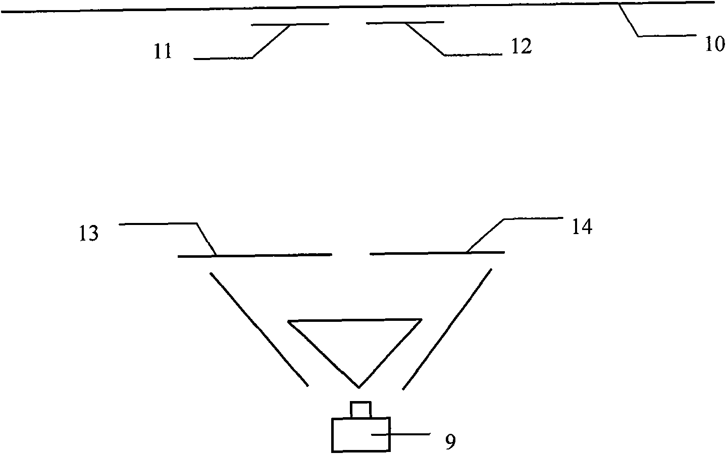
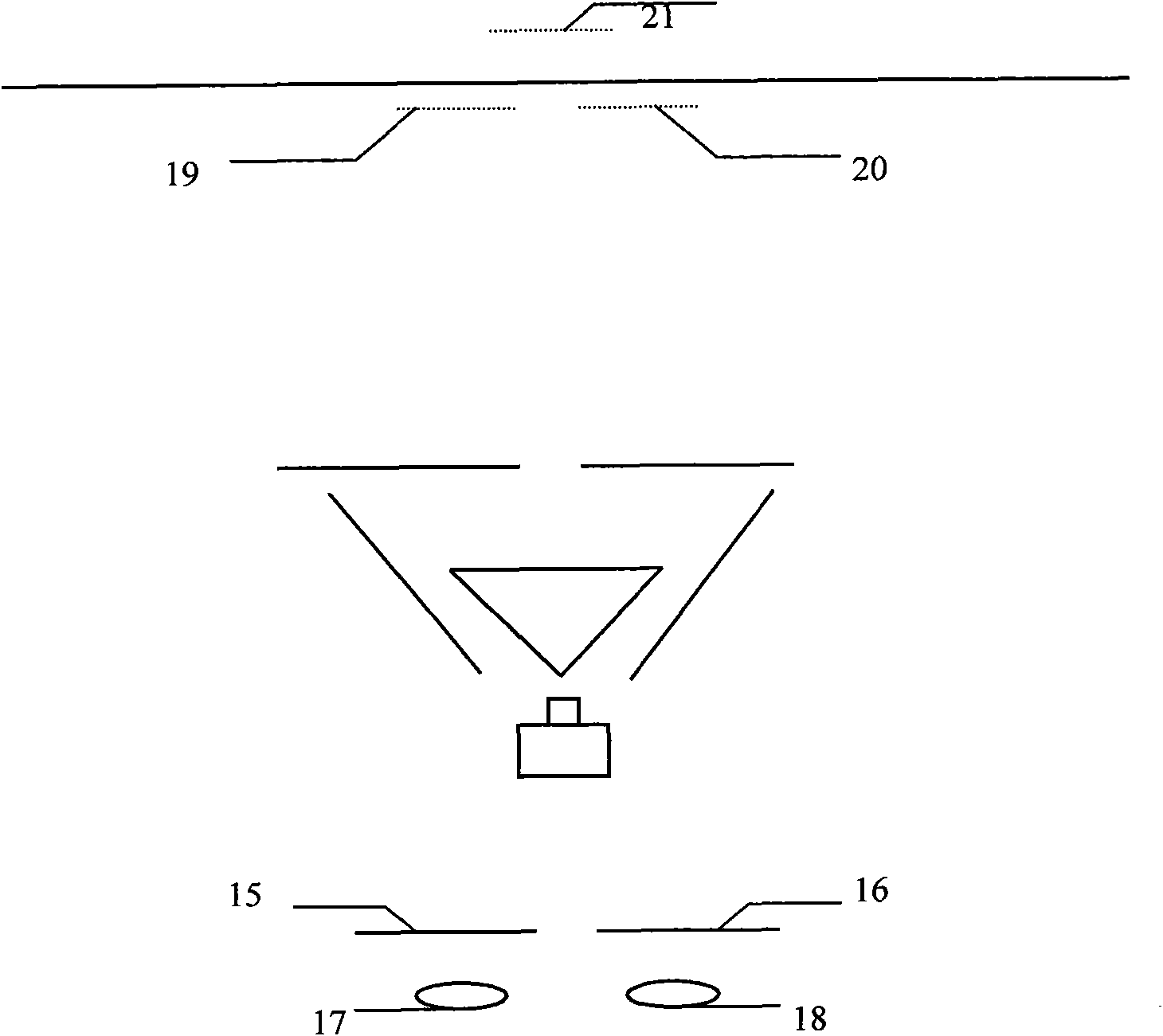
[0021] refer to figure 1 As shown, a photographing lens 5, a group of light-emitting devices and an object to be photographed 8 are shown. The spectroscopic device includes a first reflection mirror group and a second reflection mirror group, the first reflection mirror group includes a first left reflection mirror group 1 and a first right reflection mirror group 2, and the second reflection mirror group includes a second left reflection mirror group 4 and the second right reflector group 3, the angle of the first left reflector 1 and the second left reflector 4 can be adjusted according to requirements, the first left reflector 1 and the second left reflector 4 constitute the left optical path 6; The angle of a right reflector 2 and the second right reflector 3 can be adjusted according to requirements, and the first right reflector 2 and the second right...


PUM

PropertyMeasurementUnit
Angleaaaaaaaaaa

Abstract

The invention relates to a single-machine polarizing stereo film imaging system and an imaging method. The system comprises a shooting device and a projection device, wherein the shooting device comprises a camera and beam splitting devices, a group of beam splitting devices are placed in front of the lens of the camera, the beam splitting devices are provided with multiple light path channels, the multiple light path channels are provided with the same light path outlet, and the light path outlet is communicated with the lens of the camera; and the projection device comprises a projector, beam splitting devices, polarizing plates and a metal curtain, wherein one group of same beam splitting devices are placed in front of the lens of the projector, the polarizing plates with different filter directions are arranged in front of the multiple light path channels, and the light path outlet is communicated with the lens of the projector. The principle of binocular parallax is adopted, the light path of the camera is split into multiple light paths by adopting the beam splitting devices, and an image in front of the shooting lens passes through the left and right light path channels and deflects for a certain angle to reach the lens. The invention has the advantages of simple structure and compact operating steps; and because of single-machine shooting and projection, the hardware cost is greatly reduced compared with double-machine stereo films.

Description

technical field [0001] The invention belongs to a new method for shooting and imaging a stereoscopic movie, and mainly relates to a single-machine polarized stereoscopic movie imaging system and an imaging method. Background technique [0002] Three-dimensional image shooting and imaging technology is currently a popular technology in the world, and is widely used in the field of film and television production. The images it captures are visually striking, with viewers wearing special glasses that can float or sink into the curtain. With the continuous advancement and improvement of 3D film technology, many full-length 3D stereoscopic feature films have been released. Today, IMAX giant-screen movies have also begun to combine with 3D stereoscopic movies. At the Tsukuba Expo in 1985, a 70mm large-screen color stereoscopic film was exhibited. In 1959, China shot the first two-camera polarized stereoscopic film. [0003] The current three-dimensional image is to use two len...

Claims


Application Information

Patent Timeline
IPC IPC(8): G03B35/10G03B35/22G02B27/26G02B27/14G02B30/25
Inventor 周劲龚晓晖
Owner SHINING 3D TECH CO LTD
Learn More