Eureka AIR delivers breakthrough ideas for toughest innovation challenges, trusted by R&D personnel around the world.

Non-spherical lens rigid endoscope

A technology of aspheric lens and endoscope, which is applied in the field of aspheric lens group rigid tube endoscope, can solve the problems of increased financial burden, image blurring, and disappearance of patients, and achieve good operation effect, reduce use cost, and structural design reasonable effect

Inactive Publication Date: 2011-04-06
张阳德
View PDF11 Cites 19 Cited by
  • Summary
  • Abstract
  • Description
  • Claims
  • Application Information

AI Technical Summary

Problems solved by technology

That is, its light only propagates in the same medium, without considering the influence of other factors on the image quality
Assuming that the single-piece aspheric surface is required to be the thinnest and the thickness reaches a certain requirement, then the propagation energy of the light in it will be seriously lost. As the thickness increases, the formed image will gradually blur from gradually disappearing, that is, When a certain thickness is reached, it cannot be achieved with this technology
Especially after the application of optics to the field of medical technology, due to the special properties of the natural structure of the human body, the distance through which the optical path is required to pass varies widely, and physiological characteristics have special restrictions on the outline size of the product. Therefore, if this technology is applied to the field of medical imaging In addition, in order to control the cross-infection of the human body in medical surgery, the sterilization process has strict requirements. In order to improve medical safety, high temperature and high pressure methods are generally used for sterilization, but it is also proposed The concept of disposable medical devices is to avoid cross-infection, but on the one hand, the cost of surgery is higher, and the economic burden on patients is increased. On the other hand, with the increase of consumption, more medical waste will be generated. The cost is also relatively high

Method used


Image

  • Non-spherical lens rigid endoscope
  • Non-spherical lens rigid endoscope
  • Non-spherical lens rigid endoscope

Examples


Embodiment Construction

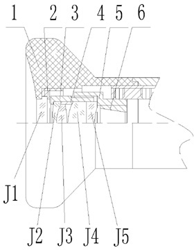
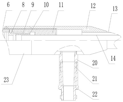
[0023] see Figure 1 to Figure 8 The eyepiece system of the aspherical lens group rigid tube endoscope in the embodiment of the present invention uses the eyepiece cover 1 as the base, and the protective sheet pressure ring 2 is connected with the screw thread matching the eyepiece cover 1 to press and fix the eye end protective sheet J1. The inner cavity of the eyepiece cover 1 is provided with a first eyepiece tube 3 and a second eyepiece tube 5, and the first eyepiece tube 3 and the second eyepiece tube 5 are connected by a screw pair to fix two groups of aspheric lenses. The first aspheric lens group is composed of aspheric lenses. Spherical lens one J2 and aspheric lens two J3 are glued together, the second aspheric lens group is made of aspheric lens three J4 and aspheric lens four J5 glued together, the first aspheric lens group and the second aspheric lens group are set An eyepiece spacer 4 is provided to ensure the installation positions of two groups of aspheric lens...


PUM


Abstract

The invention discloses a non-spherical lens rigid endoscope which comprises an ocular lens system, a microscope base system and an objective lens system, wherein the ocular lens system is connected with the microscope base system which is connected with the objective lens system, the ocular lens system is provided with an ocular lens hood, an eye end protective sheet, a protective sheet pressure ring, a first ocular lens sleeve, an ocular lens space ring, a second ocular lens sleeve, a non-spherical lens 1, a non-spherical lens 2, a non-spherical lens 3 and a non-spherical lens 4; the ocular lens hood is used as a base in the ocular lens system, the protective sheet pressure ring is connected with the ocular lens hood and presses the eye end protective sheet, the inner cavity of the ocular lens hood is provided with the first ocular lens sleeve and the second ocular lens sleeve, the inside of the second ocular lens sleeve is provided with an ocular lens diaphragm, and a rodlike lens set is arranged between the objective lens system and the ocular lens system and comprises two same rodlike lenses and concave lenses arranged at two ends of each rodlike lens. The invention has the advantages of reasonable structural design and good operation use effect, can be sterilized and disinfected under the conditions of high temperature and high pressure of 0.2bar / 134 DEG C, avoids cross-infection, lowers the use cost, and is convenient and safe.

Description

technical field [0001] The invention relates to an aspherical lens group rigid tube endoscope. Background technique [0002] In recent years, the Patent No. 200680022389.3 of the State Intellectual Property Office of China discloses a design method for a double aspheric progressive refractive index lens, specifically for a single double aspheric (such as an eyeglass) lens. That is to say, the light only propagates in the same medium, without considering the influence of other factors on the image quality. Assuming that the single-piece aspheric surface is required to be the thinnest and the thickness reaches a certain requirement, then the propagation energy of the light in it will be seriously lost. As the thickness increases, the formed image will gradually blur from gradually disappearing, that is, When a certain thickness is reached, it cannot be realized with this technology. Especially after the application of optics to the field of medical technology, due to the spe...

Claims


Application Information

Patent Timeline
IPC IPC(8): G02B23/24G02B25/00G02B13/00
Inventor 张阳德白闻喜刘廷早
Owner 张阳德
Why Eureka
Eureka Blog
Learn More