
Self-locking floor

A self-locking, flooring technology, applied in the direction of floors, buildings, building structures, etc., can solve the problems of practicality, difficulty in pulling out the tongue 31, loss of floor area, etc., to improve material yield efficiency, avoiding area loss, and reducing wood loss

Inactive Publication Date: 2011-04-06
伊善磊
View PDF7 Cites 3 Cited by
  • Summary
  • Abstract
  • Description
  • Claims
  • Application Information

AI Technical Summary

Problems solved by technology

This patent application discloses several specific implementation modes, but there are certain problems in every implementation mode, and summing up mainly contains the following points: 1. Refer to the appended drawings of this patent application document description Figure 2 to Figure 4 And Fig. 11, the tongue 9 can only be inserted in the groove 10 at a certain angle or pulled out from the groove 10, but when some special positions can only be installed in the horizontal direction, this embodiment just cannot be used, and for Processing a suitable groove 10 will inevitably cause a certain loss to the surface area of ​​the floor board; 2. Refer to the accompanying drawings of the patent application document Figure 5 to Figure 1 0, the tongue 31 can only be inserted into the groove 32 in the horizontal direction, and it is not easy to pull the tongue 31 out of the groove 32
Therefore, although the technical solution disclosed in this patent application document solves the defects existing in the installation method of floorboards before, its practicability is also affected to a certain extent due to its own structural limitations.

Method used


Image

  • Self-locking floor
  • Self-locking floor
  • Self-locking floor

Examples


Embodiment Construction

[0024] The self-locking floor of the present invention is generally processed into a long strip with uniform width, wherein the two ends in the width direction are commonly called "horizontal heads", and the two ends in the length direction are commonly called "big faces". The self-locking floor of the present invention includes two implementation modes , where the connection between the "horizontal heads" mostly adopts the first implementation mode, while the connection between the "big faces" mostly adopts the second implementation mode.

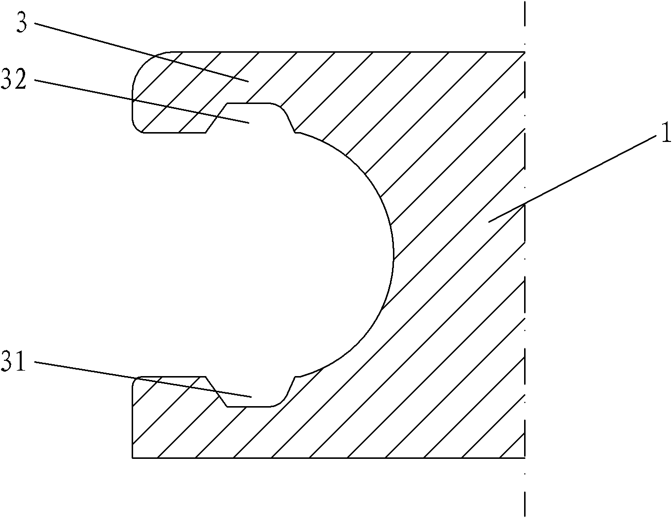
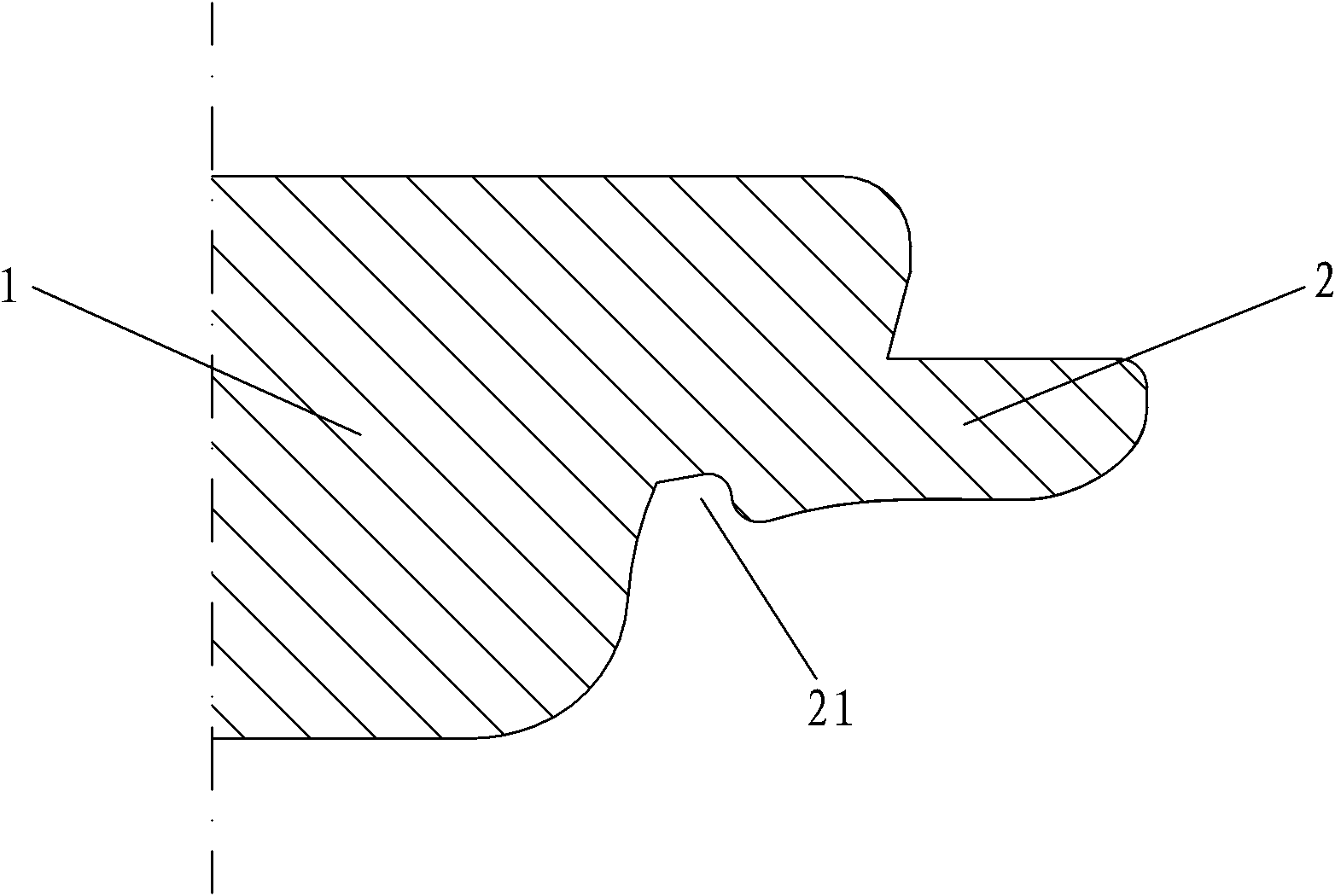
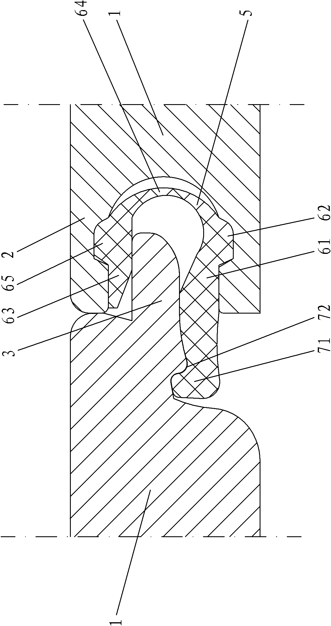
[0025] The self-locking floor of the present invention comprises a floor central part 1, a female buckle 3 is arranged at the edge of two adjacent sides of the floor central part 1, and a male buckle 2 is arranged at the edge of the other two adjacent sides. Such as figure 1 As shown, the female button 3 of the self-locking floor of the present invention (the female button at the "horizontal head" end has the same structure as the female ...


PUM


Abstract

The invention provides a self-locking floor, relating to a floor with an independent locking device and aiming to provide a self-locking floor with simple structure, simpleness and convenience for mounting and strong practicability. The self-locking floor of the invention comprises a floor central part, the edges of at least two opposite edges of the floor central part are respectively provided with connecting parts in mutual match, either connecting part comprises a tenon with a longitudinal cross section approximately shaped as a tongue and a mortise with a longitudinal cross section approximately shaped as a U-groove shape and also comprises a clamping device independent from the tenon and the mortise, the clamping device comprises a tenon clamping section suitable for being clamped by the tenon and a mortise clamping section suitable for limiting the movement of the tenon in the horizontal direction, and the tenon clamping section and the mortise clamping section are connected.

Description

technical field [0001] The invention relates to a floor, in particular to a floor with an independent locking device. Background technique [0002] Nowadays, in the field of interior floor decoration, the use of hard floors has become more common, such as solid wood floors, composite wood floors, etc. There are many ways to install such a floor. The first way is to lay the floor connecting bracket on the ground first, and then use adhesives or rivets to fix the floor on the floor connecting bracket. The disadvantage of this installation method is that it is quite complicated. And disassembly is only possible by damaging the floorboards. [0003] The second way is to process the tongue and groove structure around the floor boards, and then lay the floor boards loosely on the bottom surface. The floor boards are combined with each other by using the relationship between the tenons and grooves, usually with adhesives. Glue them together on the tongue and groove. The advantag...

Claims


Application Information

Patent Timeline
Patent Type & Authority Applications(China)
IPC IPC(8): E04F15/02
Inventor 伊善磊刘庆国姜山
Owner 伊善磊
Learn More