Rudderless course control device for ship
A control device and ship technology, applied in ship propulsion, ship parts, ship construction, etc., can solve problems such as increasing ship forward resistance
- Summary
- Abstract
- Description
- Claims
- Application Information
AI Technical Summary
Problems solved by technology
Method used
Image
Examples
Embodiment 1
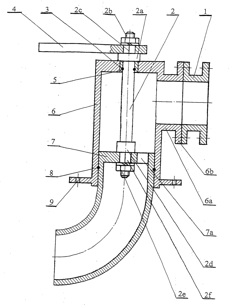
[0008] Embodiment 1 is as shown in the accompanying drawing. A hollow cylindrical body 6 with a top but no bottom has a circular through hole in the center of the top cover, a sliding bearing 5 is tightly fitted into the through hole, and an upright joystick 2 is inserted into the circular through the sliding bearing 5. In the inner cavity of the cylinder body 6, at the top of the joystick 2 exposed outside the top cover of the cylinder body 6 is an upper threaded section 2b, below the upper threaded section 2b is an upper tenon section 2c, and there is a ring under the upper tenon section 2c The shape of the shoulder blade 2a presses on the top surface of the cylinder body 6 to position the joystick 2 up and down. A horizontally placed joystick handle 4 has a square tenon hole that matches the upper tenon section 2c. The joystick handle 4 is set on the upper tenon. The segment 2c is fixed with a nut screwed on the upper threaded segment 2b, and the control handle 4 is connect...
Embodiment 2
[0012] Embodiment 2 As shown in the accompanying drawings, a rubber joystick water sealing ring 3 is embedded on the contact part between the sliding bearing 5 and the joystick 2, that is, there is a circle of grooves (or both) on the joystick 2 at this position. Groove is all arranged on the corresponding position), and joystick water sealing ring 3 is just embedded on this groove. The control rod water sealing ring 3 is used to prevent the water entering the inner cavity of the cylinder body 6 from leaking out of the cylinder body 6 along the control rod 2 . Certainly, the number of the joystick water sealing circle 3 can be 2 or 3, and the water sealing effect is better. Others are all the same as in Example 1 and will not be described again.
Embodiment 3
[0013] Embodiment 3 As shown in the drawings, a rubber right-angle elbow water seal 8 is embedded on the contact part between the right-angle elbow 7 and the cylinder body 6, that is, the right-angle elbow 7 or the cylinder body 6 at this position There is a circle of grooves (or both corresponding parts have grooves), and the right-angle elbow water sealing ring 8 is embedded in the grooves. The right-angle elbow water sealing ring 8 is used to prevent the water entering the inner cavity of the cylinder body 6 from leaking out of the cylinder body 6 along the outer surface of the right-angle elbow 7 . Of course, the number of the right-angle elbow water sealing rings 8 can be 2 or 3, and the water sealing effect is better. Others are all the same as in Example 1 and will not be described again.
PUM
 Abstract
Description
Claims
Application Information
 - Generate Ideas
- Intellectual Property
- Life Sciences
- Materials
- Tech Scout
- Unparalleled Data Quality
- Higher Quality Content
- 60% Fewer Hallucinations
Browse by: Latest US Patents, China's latest patents, Technical Efficacy Thesaurus, Application Domain, Technology Topic, Popular Technical Reports.
© 2025 PatSnap. All rights reserved.Legal|Privacy policy|Modern Slavery Act Transparency Statement|Sitemap|About US| Contact US: help@patsnap.com

