Stand-on steamer
A ship, straight-line technology, applied in ship propulsion, ship parts, ship construction, etc., can solve problems such as difficult course, and achieve the effect of increasing power
Inactive Publication Date: 2015-11-18
范庆波 +2
View PDF0 Cites 0 Cited by
- Summary
- Abstract
- Description
- Claims
- Application Information
AI Technical Summary
Problems solved by technology
[0003] The existing ship propulsion device is usually installed at the bottom of the bow. When the ship is running, the propulsion device can only drive the ship to the stern direction and cannot go backwards. When encountering a relatively narrow river, it is more difficult to change the course.
Method used
View moreImage
Smart ImageViewing Examples
Examples
Embodiment
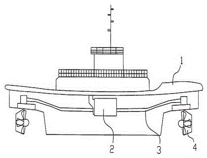
[0011] Example: According to figure 1 A straight-going ship of the present invention is shown, comprising a hull (1), a ship main engine (2) positioned in the engine room of the hull (1), a ship shafting system (3) and a ship propulsion device (4); the ship propulsion device (4 ) are two units, respectively arranged at the bottom of the bow and stern, connected with the main engine (2) of the ship through the shafting system (3); The pitch of the rudder propeller.
Login to view more PUM
Abstract
The invention discloses a stand-on steamer. The stand-on steamer comprises a hull, a marine main engine arranged in a hull cabin, a marine shafting and two marine propulsion devices, wherein the two marine propulsion devices are respectively arranged at the bottoms of a bow and a stern and are connected with the marine main engine through the marine shafting. The marine propulsion devices are steering oars which can be in full circle swinging of 360 degrees and have controllable pitch. The stand-on steamer disclosed by the invention has the benefits that the two marine propulsion devices are respectively arranged at the bottoms of the bow and the stern, so that driving force can be respectively provided towards reverse directions, and the steamer is convenient to change course in a narrow watercourse; the steering oars in the full circle swinging of 360 degrees and with controllable pitch are adopted, so that the propulsion devices can be adjusted to provide the driving force towards the same direction, and the travelling power of the steamer travel in increased.
Description
technical field [0001] The invention belongs to the technical field of ship engineering, and in particular relates to a straight-going ship. Background technique [0002] As a kind of modern tools, ships are mainly used for transportation, transportation, fishing of aquatic organisms, development of seabed mineral deposits, harbor services, sports tours, scientific investigation and measurement, engineering operations, rescue, national defense and military, etc. and other fields. Existing ship power sources mainly contain powers such as manpower, sails, and electric motors. Large ships that are propelled by machines can be called ships. [0003] The existing ship propulsion device is usually arranged at the bottom of the bow. When the ship is running, the propulsion device can only drive the ship to the stern direction and cannot go backwards. When encountering a relatively narrow river, it is difficult to change the course. Contents of the invention [0004] The object...
Claims
Login to view more Application Information
Patent Timeline
IPC IPC(8): B63H5/08B63H5/125B63H25/42
Inventor 范庆波王婉玉张鹏豪
Owner 范庆波
- R&D Engineer
- R&D Manager
- IP Professional
Why Eureka
- Industry Leading Data Capabilities
- Powerful AI technology
- Patent DNA Extraction
Try Eureka
Browse by: Latest US Patents, China's latest patents, Technical Efficacy Thesaurus, Application Domain, Technology Topic.
© 2024 PatSnap. All rights reserved.Legal|Privacy policy|Modern Slavery Act Transparency Statement|Sitemap