
High-speed rotary atomization and absorption device for desulfurizing and removing smoke dust

A technology of high-speed rotation and absorption device, applied in combination devices, chemical instruments and methods, and dispersed particle separation, etc., can solve the problems of low absorption and treatment efficiency of harmful substances, low efficiency of harmful waste gas treatment, and high equipment investment cost, and achieve a one-time The effect of low input cost, significant use effect, low manufacturing and maintenance cost

Inactive Publication Date: 2011-03-30
易敏华
View PDF1 Cites 6 Cited by
  • Summary
  • Abstract
  • Description
  • Claims
  • Application Information

AI Technical Summary

Problems solved by technology

[0002] At present, the commonly used flue gas purification treatment technologies include: wet treatment and dry treatment, but the absorption and treatment efficiency of these technical devices for harmful substances is relatively low, especially for refractory, non-hydrophilic smoke, containing SO 2 , NO and CO chemical gases and other harmful waste gas treatment efficiency is low, the operation effect is unstable, and the application limitations are large. In practical applications, a combination of various technical equipment is usually required to achieve better results. For example, the Chinese patent No. 200320122391.1 The waste incineration flue gas water-cooled purification device adopts flue gas high-temperature water-cooled cyclone dust removal, water heat exchange, air preheating, dry desulfurization (acid removal), bag dust removal and other combined flue gas purification devices. Manufacturing, equipment investment costs are high

Method used


Image

  • High-speed rotary atomization and absorption device for desulfurizing and removing smoke dust
  • High-speed rotary atomization and absorption device for desulfurizing and removing smoke dust
  • High-speed rotary atomization and absorption device for desulfurizing and removing smoke dust

Examples


Embodiment Construction

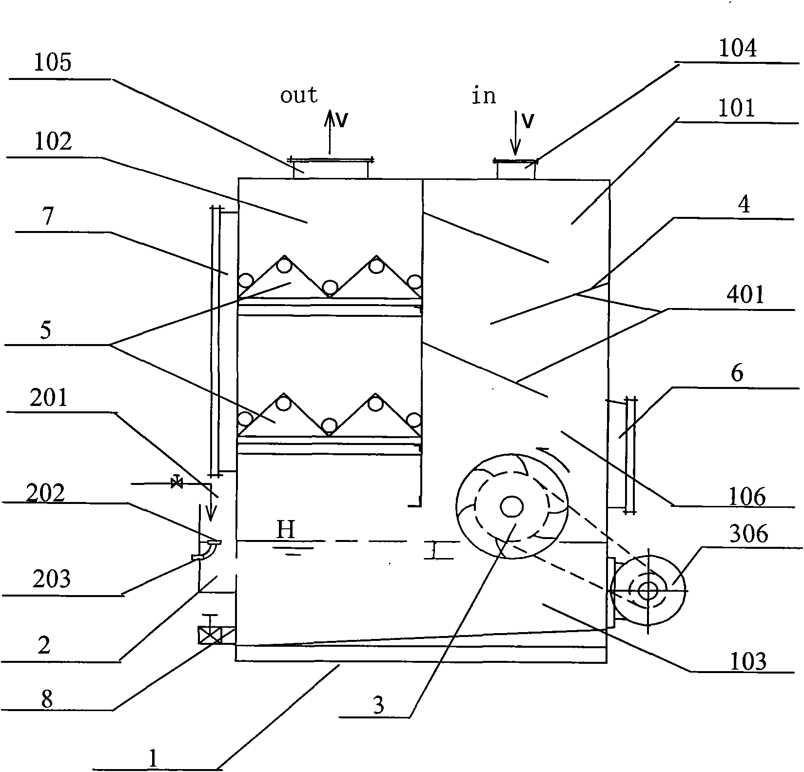
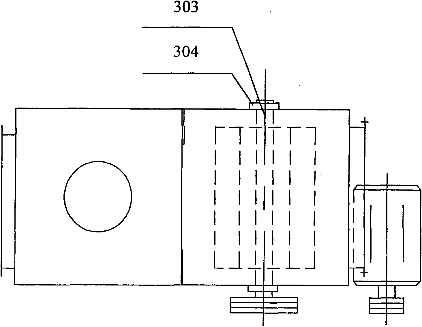
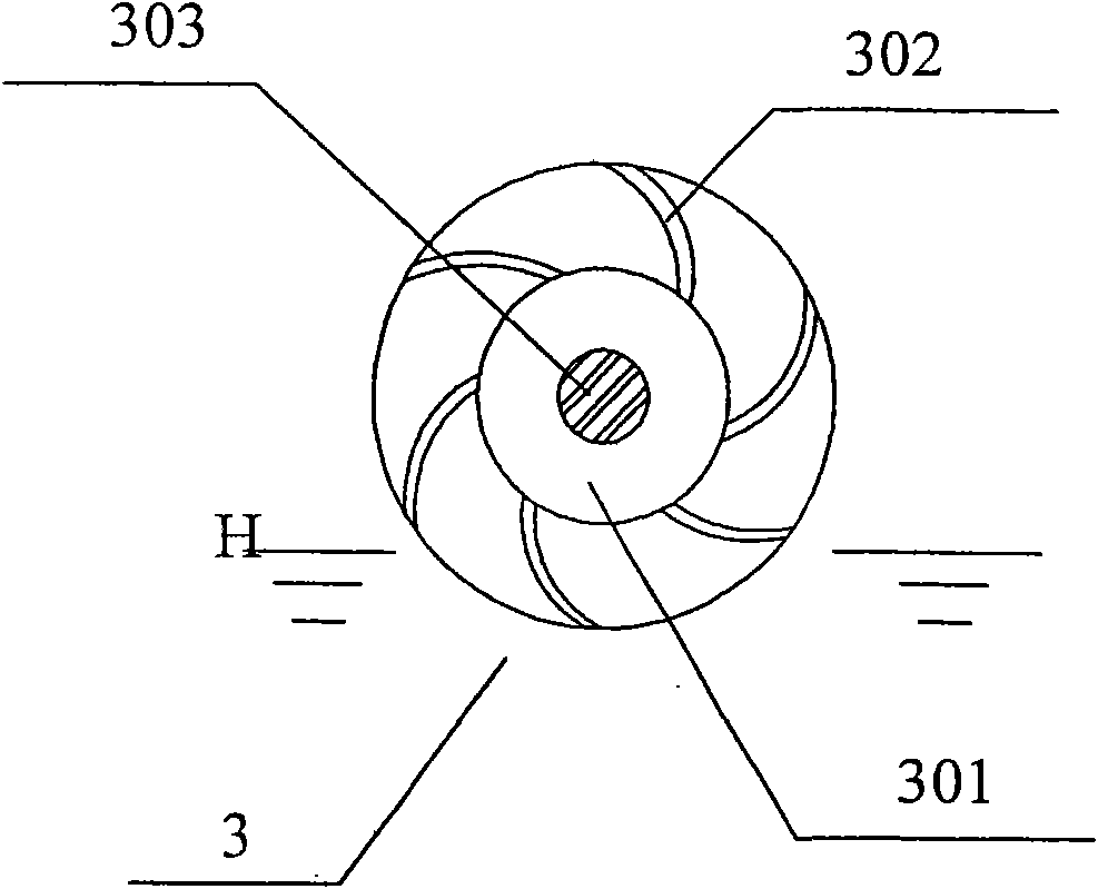
[0026] Referring to the accompanying drawings, the high-speed rotary atomization absorption device for desulfurization and dust removal of the present invention includes a cavity 1, and a solvent tank 103 is arranged at the bottom of the cavity 1, and the cavity above the solvent tank 103 is divided into two air inlet ends whose bottoms communicate with each other. The chamber 101 and the exhaust end chamber 102, the intake port 104 and the exhaust port 105 are respectively arranged on the intake end chamber 101 and the exhaust end chamber 102, and a flow guiding device is arranged in the intake end chamber 101 4. The guide device includes several guide plates 401 to form a labyrinth design and installation. The secondary microfiltration device 5 is installed in the exhaust end chamber 102, and the rotary aeration device 3 is installed in the intake end chamber 101. At the bottom, in this embodiment, the rotary aeration device 3 includes a runner 301 and a transmission shaft 30...


PUM


Abstract

The invention provides a high-speed rotary atomization and absorption device for desulfurizing and removing smoke dust. The device comprises a cavity, wherein the bottom of the cavity is provided with a solvent trough, and the cavity above the solvent trough is divided into two chambers of which the bottoms are communicated; the two chambers are respectively provided with an air inlet and an air exhaust port which are respectively used for inputting smoke (waste gas) to be treated and outputting treated tail gas, the bottom of the chamber with the air inlet is provided with a rotary aerating device, and a part of a rotating wheel blade of the rotary aerating device is soaked into a solution in the solvent trough; the chamber with the air exhaust port is internally provided with at least one stage of microfiltration device; the liquid level of the solvent trough can be regulated and controlled; and if necessary, a flow guide device and a plurality of stages of rotary aerating devices can be arranged in the cavity. The device can be widely applied to the fields of exhaust smoke purification for diesel generator rooms and power plants, the desulfurization and dust removal of smoke for industrial waste gas and oily fume in restaurants and institution kitchens, and the like.

Description

Technical field: [0001] The invention relates to a fume purification device, in particular to a high-speed rotary atomization absorption device for desulfurization and fume removal. Background technique: [0002] At present, the commonly used flue gas purification and treatment technologies are: wet treatment and dry treatment, but the absorption and treatment efficiency of these technical devices for harmful substances is relatively low, especially for refractory, non-hydrophilic smoke, SO 2 , NO and CO chemical gases and other harmful waste gas treatment efficiency is low, the operation effect is unstable, and the application is limited. The waste incineration flue gas water-cooled purification device adopts a combination of flue gas high-temperature water-cooled cyclone dust removal, water heat exchange, air preheating, dry desulfurization (acid removal), bag dust removal and other combined flue gas purification devices. Manufacturing, equipment investment costs are high...

Claims


Application Information

Patent Timeline
IPC IPC(8): B01D50/00
Inventor 易敏华余球精
Owner 易敏华
Learn More