Antenna used for radio frequency identification device system and configuration method thereof, and radio frequency identification reader-writer

A wireless radio frequency and identification system technology, applied in the field of RFID readers, can solve problems such as disasters, difficulty in ensuring phase offset, and difficulty in mass production of antennas

Inactive Publication Date: 2011-03-23
SIEMENS AG
View PDF1 Cites 8 Cited by
  • Summary
  • Abstract
  • Description
  • Claims
  • Application Information

AI Technical Summary

Problems solved by technology

RFID systems used in manufacturing must answer the following questions: When does a tag enter the reading zone? When is the tag directly in front of the reader antenna? When does the tag leave the read zone? Once the RFID system cannot control the reading area, catastrophic consequences may occur
The phase offset determined by these parameters is greatly affected by the signal frequency. In a large signal bandwidth range, it is difficult to guarantee a constant phase offset with the above fixed parameters. Therefore, the above scheme is very difficult. Difficult to guarantee in-phase current distribution across the entire signal bandwidth
At the same time, the antenna scheme based on the discontinuous loop is very sensitive to the width of the gap and the conductor length of the overlapping part, which causes certain difficulties for the mass production of the antenna

Method used


Image

  • Antenna used for radio frequency identification device system and configuration method thereof, and radio frequency identification reader-writer
  • Antenna used for radio frequency identification device system and configuration method thereof, and radio frequency identification reader-writer
  • Antenna used for radio frequency identification device system and configuration method thereof, and radio frequency identification reader-writer

Examples


Embodiment Construction

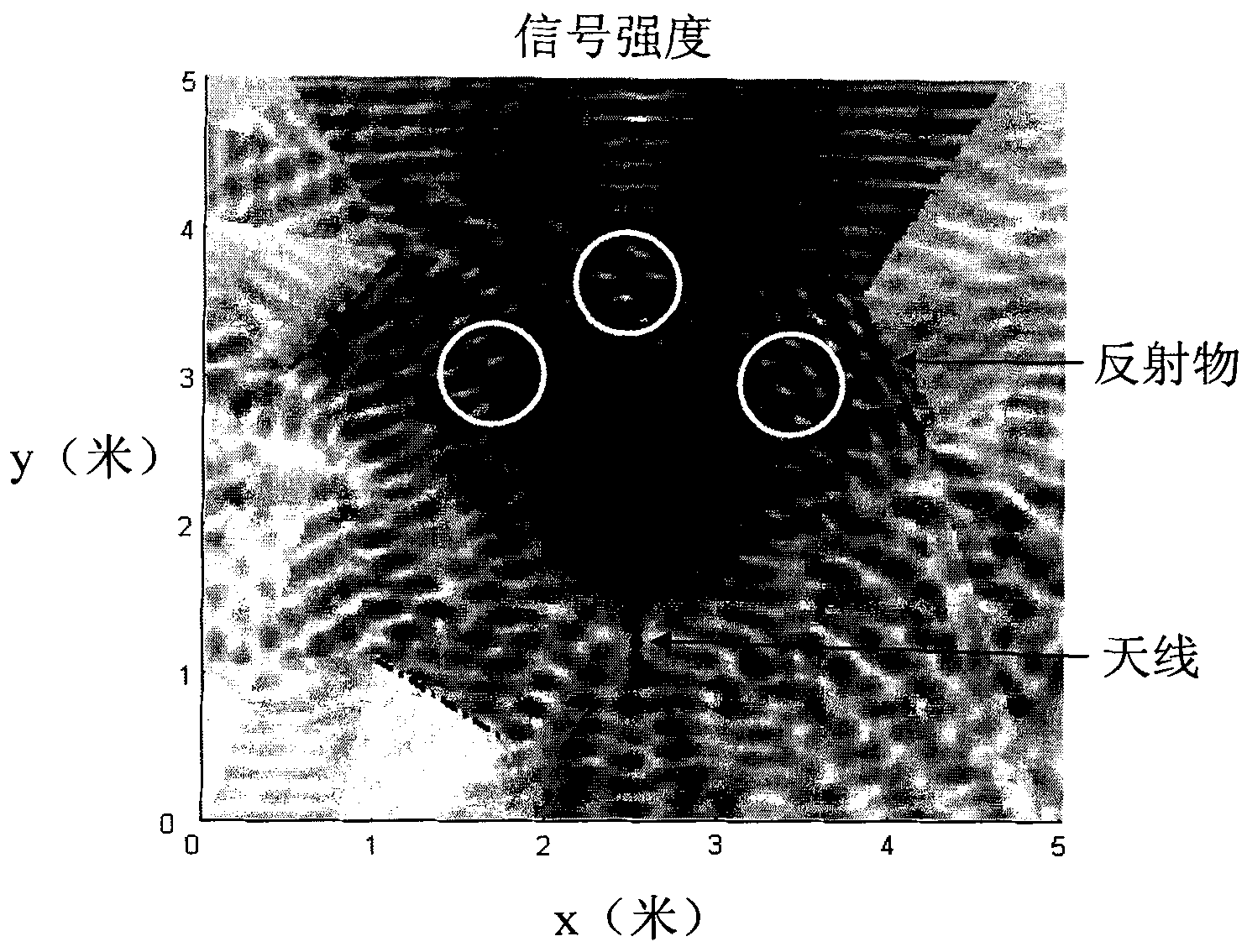
[0042] The design principle of the antenna according to the invention is derived from the standing wave theory.

[0043] According to the standing wave theory, if the end of the conductor line is open circuit, short circuit or connected to a pure reactive load, the incident electric wave will be completely reflected, and the reflected wave will be superimposed with the incident wave, thus forming a standing wave on the conductor line. When the end of the conductor line is open, the incident wave current and the reflected wave current have the same amplitude and opposite phase at the end of the conductor line. The end of the conductor line is a current wave node. From this node, every half wavelength along the conductor line A current wave node is located at the length of , and from each current wave node, a current antinode is located along the length of a quarter wavelength along the conductor line. The current phase between every two current wave nodes is always the same, th...


PUM


Abstract

The invention provides an antenna for an RFID (Radio Frequency Identification Device) system, which comprises a conductor line, wherein the conductor line comprises at least two loop parts and at least one connecting part, the at least two loop parts are configured along one loop and are discontinuous in the space; in every two successive loop parts, the tail end of the first loop part is connected with the starting end of the second loop part through a connecting part which is configured in a manner of departing from the loop; when an exciting signal is fed into the conductor line, the at least two loop parts and the at least one connecting part generate an exciting current, and the exciting current in the at least two loop parts further generates a magnetic field. Enough antenna size is realized in an UHF RFID through the antenna, and the requirement for reading distance of the UHF RFID reader-writer is met. In addition, the invention also provides a substituent solving scheme of the antenna, deformation and a configuration method thereof, and an RFID reader-writer with the antenna of the invention.

Description

technical field [0001] The invention relates to radio frequency identification (RFID) technology, in particular to an antenna for an RFID system, a configuration method thereof and an RFID reader with the antenna. Background technique [0002] In recent years, ultra-high frequency (UHF) RFID technology has received more and more attention. Due to the ability to identify hundreds of individual objects per second, UHF RFID creates a large number of opportunities in logistics-related applications. However, traditional far-field UHF RFID communication systems are often affected by multipath propagation, that is, the transmitted radio signal reaches the receiver through multiple propagation paths. Reflection and refraction in the surrounding environment can lead to multiple different propagation paths for radio signals, resulting in different path delays, phase offsets, and signal attenuation. Depending on the specific signal frequency used, the individual multipath signal comp...

Claims


Application Information

Patent Timeline
IPC IPC(8): H01Q1/22H01Q1/36H01Q3/26H01Q3/34G06K17/00
CPCH01Q7/00H01Q1/2216H01Q21/20
Inventor 袁勇喻丹霍尔斯特・迪特
Owner SIEMENS AG
Why Eureka
Try Eureka