
Centrifugal bionic coupling pump

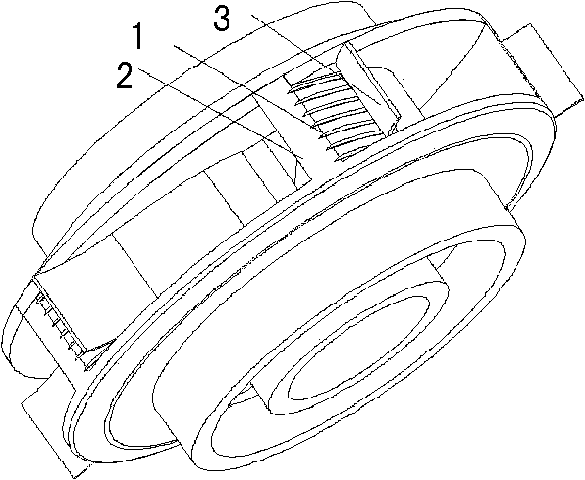
A centrifugal, pump casing technology, applied in the field of agricultural or industrial fluid machinery, can solve problems such as reduced efficiency and difficulty, and achieve the effects of improving efficiency, preventing cavitation, and improving corrosion resistance.

Inactive Publication Date: 2011-03-09
JILIN UNIV
View PDF4 Cites 8 Cited by
  • Summary
  • Abstract
  • Description
  • Claims
  • Application Information

AI Technical Summary

Problems solved by technology

Since most types of water pumps are relatively mature machines, it is very difficult to increase pump efficiency by 1% from the design point of view, and if the operation of the water pump deviates from the high efficiency point of the design, the actual operating efficiency will be far more than reduced by 1%.

Method used


Image

  • Centrifugal bionic coupling pump
  • Centrifugal bionic coupling pump
  • Centrifugal bionic coupling pump

Examples


Embodiment 1

[0027] The rib-shaped bionic non-smooth shape is processed on the side of the impeller. The cross-section of the rib-shaped non-smooth structure is an equilateral triangle, the side length is 0.9mm, and the distance between the ribs is 2.7mm. The resin material with a Shore hardness of 50 is attached. In the impeller of the water pump, in the entire flow section, compared with the traditional water pump without bionic coupling design, the efficiency in the entire effective flow section (the effective flow section of the 200QJ50-26 centrifugal water pump is 40m3 ~ 60m3) has been improved. Such as image 3 shown, at a flow rate of 55m 3 , the efficiency is increased by about 2%, and the flow rate is 65m 3 , the efficiency increased by 5%.

Embodiment 2

[0029] The pit-like bionic non-smooth shape is processed on the side of the impeller, the radius of the pit is 0.5mm, the distance between the pits is 1mm, and the PTU material with a Shore hardness of A50 is coated, which is different from the traditional water pump without bionic coupling design. In the effective flow range, the efficiency is improved, and the flow rate is 60m 3 , the efficiency is increased by about 2%, and the head is improved in the whole flow range, such as Figure 4 shown, especially at flow rates of 60m 3 , The head has been increased by about 1.75m, and the increase rate has reached 6.7%.

Embodiment 3

[0031] The rib-like bionic non-smooth shape is processed on the back of the impeller. The side length of the rib is 1.3mm, the spacing is 2.6mm, and the polyurethane material with Shore hardness of A50 is coated. Compared with the traditional water pump without bionic coupling design, the In the effective flow section, the efficiency is at a flow rate of 60m 3 , the efficiency increased by nearly 2%. In the whole flow section, the head was improved, and the head increased by an average of 3.4m, with an increase of 13.11%.

[0032] The efficiency-flow curves and head-flow curves of the bionic coupled water pumps in the above three implementation examples and the traditional water pumps without coupling design are as follows: image 3 , Figure 4 shown.


PUM

PropertyMeasurementUnit
Radiusaaaaaaaaaa
Thicknessaaaaaaaaaa
Side lengthaaaaaaaaaa

Abstract

The invention relates to a centrifugal bionic coupling pump, belonging to various fields such as the fluid machinery. The impeller of the pump adopts the combination of a bionic coupling impeller and a common pump shell, the combination of a bionic coupling pump shell and a common impeller or the combination of a bionic coupling impeller and a bionic coupling pump shell, wherein the bionic coupling impeller or the guide vane in the bionic coupling pump shell is provided with bionic unsmoothed structures; the bionic unsmoothed structures are rib-shaped or pit-shaped, the rib-shaped or pit-shaped unsmoothed structures are distributed along the impeller passage and the guide vane in the pump shell correspondingly; the cross section of each rib is a regular triangle with the side length of 0.5-1.3mm, the distance between the ribs is 0.5-3.9mm; and the pit radius of each pit-shaped structure is 0.5-1.3mm, and the distance between the pits is 0.5-3.9mm. The centrifugal bionic coupling pump solves the problems of the existing centrifugal pump that the efficiency is low, the cavitation phenomenon is easy to generate, etc. The performance of the centrifugal pump can be improved and the efficiency and delivery lift of the centrifugal pump can be increased.

Description

Technical field: [0001] The present invention relates to agricultural or industrial fluid machines. technical background: [0002] Water pumps are general machinery widely used in the national economy. According to relevant statistics, in China, the power consumption of water pumps accounts for about 20% of the country's total power generation, and its fuel consumption accounts for about 5% of the country's total fuel consumption. Now, water pumps have become the most widely used motors in addition to motors. General Machinery. Therefore, it is imperative to improve the operating efficiency of the water pump, save energy and reduce consumption. Since most types of water pumps are relatively mature machines, it is very difficult to increase the pump efficiency by 1% from the design point of view, and if the operation of the water pump deviates from the design high-efficiency point, the actual operation efficiency is far more than 1%. Therefore, a new concept is needed to i...

Claims


Application Information

Patent Timeline
IPC IPC(8): F04D1/00F04D29/22F04D29/42
Inventor 任露泉田丽梅陈庆海卜兆国廖庚华李文渊
Owner JILIN UNIV
Learn More