Method for arranging display equipment software and method for writing control parameters into FLASH
A technology of control parameters and layout method, which is applied in the layout of display device software, control parameters written into FLASH field, can solve problems such as inability to guarantee the accuracy of program modification, complex MCU control program, loss of control parameters, etc., to reduce complexity and risk, reduce the risk of data loss, and improve efficiency
- Summary
- Abstract
- Description
- Claims
- Application Information
AI Technical Summary
Problems solved by technology
Method used
Image
Examples
Embodiment 1
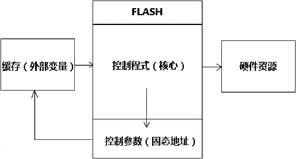
[0022] a kind of like figure 1 The layout method of the display device software shown is to separate the control program of the software from the control parameters, store some unchanging control parameters and preset values in FLASH (flash memory), and set it as a protected state, so that read only. The method of separating the control program and the control parameters is to separate the two by modularization. All the required parameters of the control program part use global variables to become the control module independently. In the control parameter part, the control parameters are transferred from the FLASH (flash memory) The pre-planned fixed positions are read out and assigned to global variables to form an initialization control parameter module, and these assigned global variables are directly called in the control link. When burning the control parameters to FLASH (flash memory), when the software is still in the document state, set some unchanging control param...
Embodiment 2
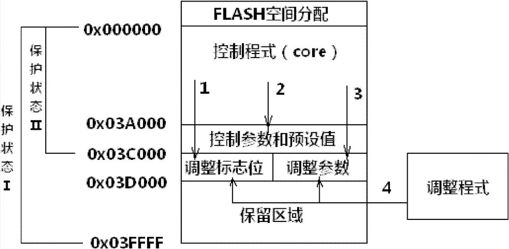
[0025] The method that control parameter of the present invention is written into FLASH:
[0026] 1. Plan the data storage structure in the free space
[0027] According to the setting method of the status register of FLASH (flash memory), plan the storage location of the control parameters in the free space. The following takes EON25F20 FLASH IC as an example to illustrate, the status register control mode of this IC is as follows:
[0028]
[0029] We plan the control program at 0x000000-0x039FFF,
[0030] We plan the control parameters at 0x03A000-0x03BFFF,
[0031] The adjusted status bits and adjusted control parameters are planned at 0x03C000-0x03CFFF
[0032] The reason for this setting is to facilitate the adjustment of the data write-protected area. When no adjustment is needed, the status register of FLASH is set to "111", fully protected and only readable. When it is necessary to adjust the storage, pull down the hardware write protection, set the status reg...
PUM
 Abstract
Description
Claims
Application Information
 - R&D
- Intellectual Property
- Life Sciences
- Materials
- Tech Scout
- Unparalleled Data Quality
- Higher Quality Content
- 60% Fewer Hallucinations
Browse by: Latest US Patents, China's latest patents, Technical Efficacy Thesaurus, Application Domain, Technology Topic, Popular Technical Reports.
© 2025 PatSnap. All rights reserved.Legal|Privacy policy|Modern Slavery Act Transparency Statement|Sitemap|About US| Contact US: help@patsnap.com


