
Method for designing partially compensatory lens by taking slope as optimization objective

A technology for compensating lenses and optimizing targets, which is applied in the field of aspheric surface detection, can solve problems such as inability to directly optimize the wavefront slope, unreasonable optimization target settings, and incomplete and reliable optimization results, so as to simplify design difficulty, reduce detection costs, and set simple effect

Inactive Publication Date: 2011-02-16
BEIJING INSTITUTE OF TECHNOLOGYGY
View PDF2 Cites 6 Cited by
  • Summary
  • Abstract
  • Description
  • Claims
  • Application Information

AI Technical Summary

Problems solved by technology

[0008] The purpose of the present invention is to solve the problem that the optimization target setting is unreasonable, the optimization result is not comprehensive and reliable, and the existing optical design software cannot directly optimize the wavefront slope when the wave aberration method is used to design a partially compensated lens in the prior art. A design method of partial compensation lens with the slope as the optimization target, which optimizes the full-aperture light, and can reduce the design difficulty of the partial compensation lens as much as possible under the premise that interference fringes can be detected

Method used


Image

  • Method for designing partially compensatory lens by taking slope as optimization objective
  • Method for designing partially compensatory lens by taking slope as optimization objective
  • Method for designing partially compensatory lens by taking slope as optimization objective

Examples


Embodiment

[0037] A partially compensated lens design method with slope as the optimization objective is implemented as follows:

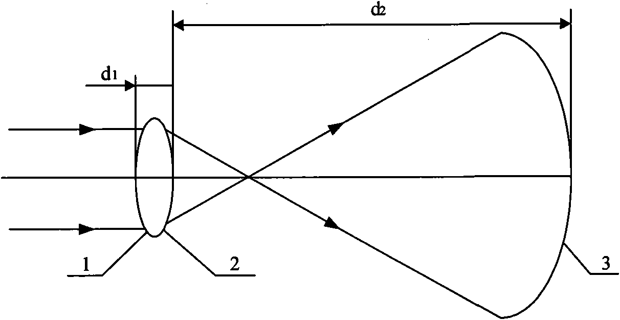
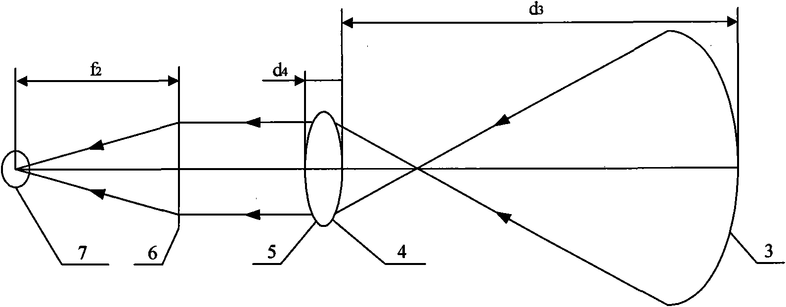
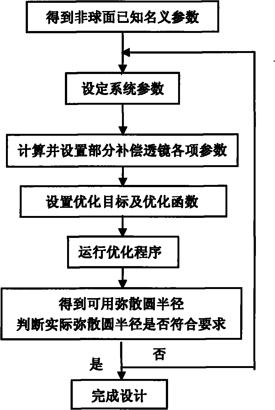
[0038] It is known that the diameter of the measured aspheric surface is D'=580mm, and the radius of curvature of the vertex is R 0 =1179.447mm, eccentricity k=-0.499365, the specific steps of designing a partial compensation lens to detect the machining error of the measured aspheric surface are as follows image 3 shown, including:

[0039] Step 1: Set system parameters

[0040] Set the entrance pupil diameter D=80mm and wavelength λ=550nm as needed;

[0041] Step 2: Calculate the optical parameters of the partially compensated lens

[0042] For most aspheric surfaces, simply using a singlet lens as a partial compensation lens will suffice. First, open the editing bar of the Lens Data Editor of the ZEMAX optical design software. There are already three surfaces in the editing bar, which are the object surface OBJ, the aperture STO and the image surface ...


PUM


Abstract

The invention relates to a method for designing a partially compensatory lens by taking a slope as an optimization objective and belongs to the technical field of aspherical detection. The method comprises the following steps of: setting system parameters, namely setting entrance pupil diameter D and wavelength lambda as required by using ZEMAX optical design simulation software which is widely used in the field of photoelectron as a design platform; calculating the optical parameters of the partially compensatory lens; and arranging a reflected light path, and calculating structural parameters of a partially compensatory detection system to take the slope as the optimization objective. The method is simple and fast, is easy to implement, optimizes light rays in the full aperture range, performs comprehensive and reasonable analysis, realizes the detection and optimization of the maximum slope of residual wave aberration by using the radius of a confusion circle as the optimization objective, simplifies the design difficulty of the partially compensatory lens under the condition of ensuring distinguishable interference fringes, and can expend the detection scope for a compensator so as to reduce detection cost and improve detection speed.

Description

technical field [0001] The invention relates to a design method of a partial compensation lens with slope as an optimization target, belonging to the technical field of aspheric surface detection. Background technique [0002] The traditional zero compensation test is a test method for small residual wave aberration, which needs to completely compensate the normal aberration of the measured aspherical surface through the wavefront of the zero compensator, so it is usually necessary to use a complex lens group as the zero compensator, Design and processing are difficult. The partial compensation detection method is a newly developed aspheric surface detection technology. Different from the zero compensation test, it does not require the light after the partial compensation lens to completely compensate the normal aberration of the aspheric surface. In the actual interference optical path, the measured aspheric surface is compensated by the wavefront after the partial compens...

Claims


Application Information

Patent Timeline
IPC IPC(8): G01M11/02G02B27/00G02B3/02
Inventor 郝群朱秋东谢枫
Owner BEIJING INSTITUTE OF TECHNOLOGYGY
Learn More