
Remote control multi-angle positioning device

A positioning device, multi-angle technology, applied in the direction of measuring device, material analysis through optical means, instruments, etc., can solve the problems of poor positioning accuracy, error, low accuracy and precision, and meet the requirements of multi-angle accurate measurement Effect

Active Publication Date: 2012-05-30
CENT FOR EARTH OBSERVATION & DIGITAL EARTH CHINESE ACADEMY OF SCI
View PDF0 Cites 0 Cited by
  • Summary
  • Abstract
  • Description
  • Claims
  • Application Information

AI Technical Summary

Problems solved by technology

[0005] 1. Since the original method cannot guarantee that the probe always detects the same point on the water surface during the multi-angle ion-water radiation measurement process, it is assumed that the water surface observed in the experiment is the same, which will cause errors
[0006] 2. The visual estimation of azimuth and zenith angle has a large error, so the positioning accuracy of the traditional method is poor
[0007] 3. The traditional method of visually determining the measurement angle cannot meet the requirements of multi-angle measurement of water-leaving radiation
[0008] 4. The observer of the traditional method is very close to the object of observation, which will affect the measurement accuracy
[0009] Therefore, the accuracy and precision of measurement by traditional methods are very low, which cannot meet the data quality requirements of remote sensing quantitative experiments. At present, there is no relatively mature device for multi-angle measurement of water radiation at the same point on the water surface in the world.

Method used


Image

  • Remote control multi-angle positioning device
  • Remote control multi-angle positioning device
  • Remote control multi-angle positioning device

Examples


Embodiment Construction

[0040] The invention discloses a remote control multi-angle positioning device, which can position the probe of a spectrometer with high precision, reduce the influence of observers on the observation results by means of remote control, and make the measurement results more accurate.

[0041] The following will clearly and completely describe the technical solutions in the embodiments of the present invention with reference to the accompanying drawings in the embodiments of the present invention. Obviously, the described embodiments are only some, not all, embodiments of the present invention. Based on the embodiments of the present invention, all other embodiments obtained by persons of ordinary skill in the art without making creative efforts belong to the protection scope of the present invention.

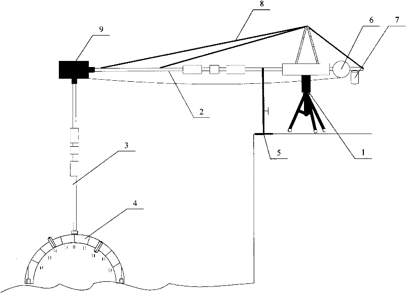
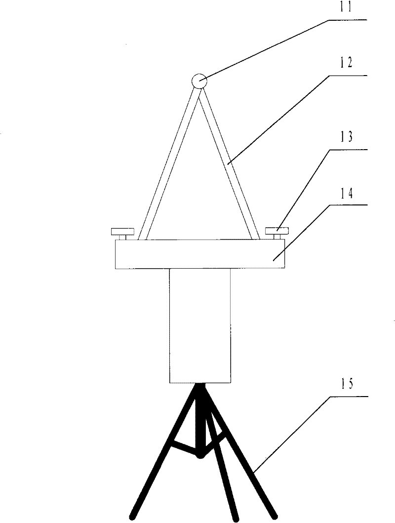
[0042] see figure 1 , figure 1 It is a schematic structural diagram of a remote control multi-angle positioning device provided by an embodiment of the present invention.

[0...


PUM


Abstract

The invention discloses a remote control multi-angle positioning device comprising a support body, a horizontal rod, a rotating device, a vertical rod, a semicircular frame, a hand wheel and a transmission shaft, wherein, the support body is provided with a horizontal hollow pipe; the horizontal rod is arranged in the horizontal hollow pipe in an insertion manner; the rotating device is fixed on one end of the horizontal rod, and comprises a worm gear; one end of the vertical rod is connected with the support shaft of the worm wheel; the semicircular frame is fixed on the other end of the vertical rod, and is provided with a probe slot; the hand wheel is arranged on the other end of the horizontal rod in a rotatable manner; one end of the transmission shaft is connected with the hand wheel; and the other end of the transmission shaft is connected with the worm. The device of the invention can accurately adjust the positioning of the probe in X, Y, Z three-dimensional space and utilizes the selection of the lengths of the rod bodies (the horizontal rod and the vertical rod) in horizontal and vertical directions to adjust the distance of the probe and a detected object, thus greatlysatisfying the requirements of multi-angle accurate measurement.

Description

technical field [0001] The invention relates to the technical field of detection equipment, and more specifically, to a remote-controlled multi-angle positioning device. Background technique [0002] Water-leaving radiation refers to the radiation energy that enters the water body, absorbs, scatters, and transmits the water body, and finally leaves the water surface. Water-leaving radiation has become an important physical quantity in water quality remote sensing research because it contains information about water bodies. [0003] When using a spectrometer to measure water-leaving radiation on the water surface, the above-water measurement method is generally followed. The traditional method is to hold a pole, install a spectrometer probe on one end of the pole, and visually estimate the azimuth angle and zenith angle of the probe to meet the observation geometric angle required by the code. In addition, due to the two-way nature of water-leaving radiation, there are grea...

Claims


Application Information

Patent Timeline
Patent Type & Authority Patents(China)
IPC IPC(8): G01N21/01
Inventor 张兵申茜李俊生宋阳吴迪张浩吴远峰
Owner CENT FOR EARTH OBSERVATION & DIGITAL EARTH CHINESE ACADEMY OF SCI
Learn More