Optical path switching interface mechanism for fiber channel test of relay protection device
A technology of relay protection device and fiber channel, applied in the direction of optical fiber transmission, measuring device, circuit breaker test, etc. Increased attenuation and other problems, to improve the level of on-site protection calibration and maintenance, solve the problem of poor contact, and shorten the switching time
- Summary
- Abstract
- Description
- Claims
- Application Information
AI Technical Summary
Problems solved by technology
Method used
Image
Examples
Embodiment Construction
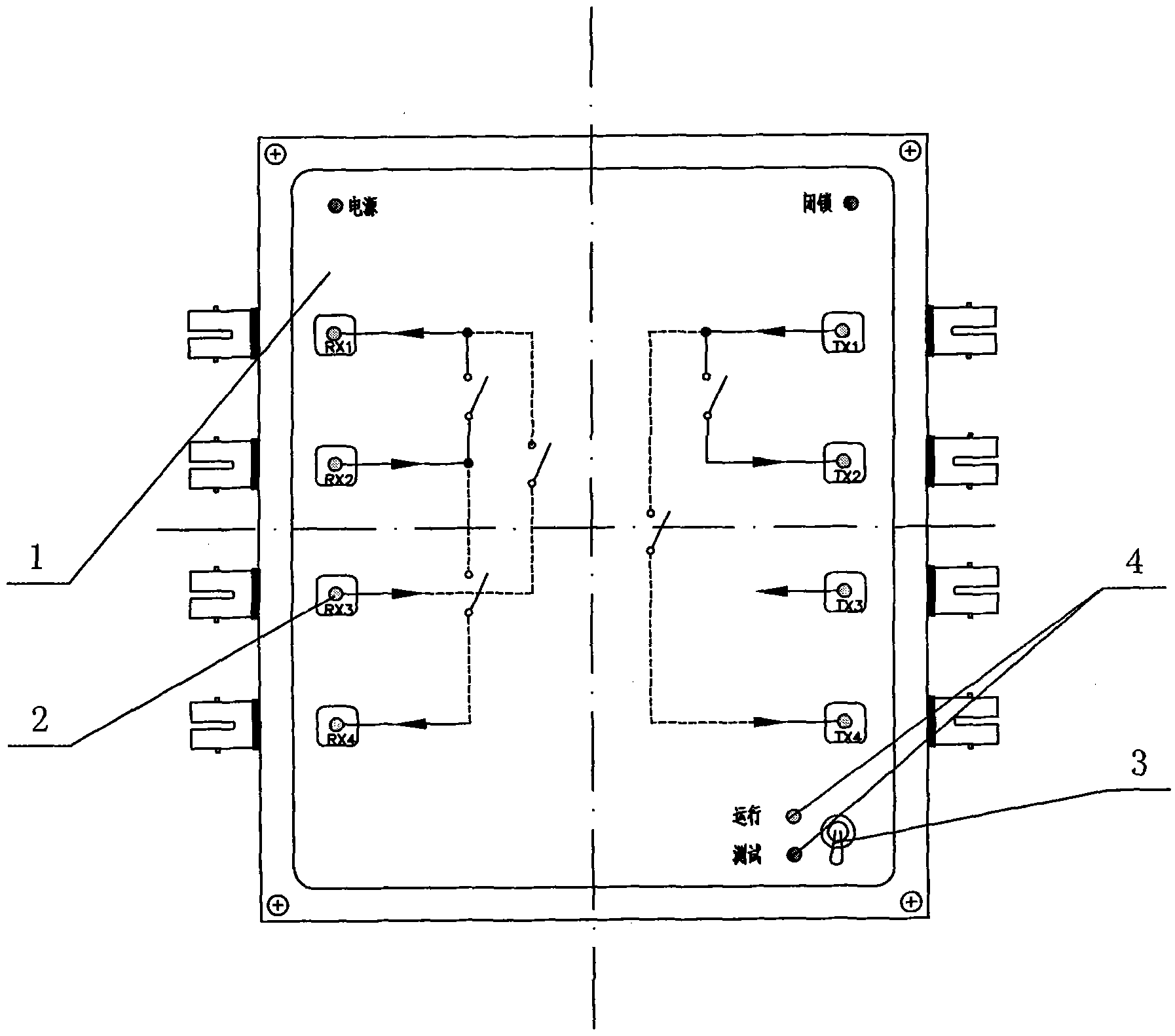
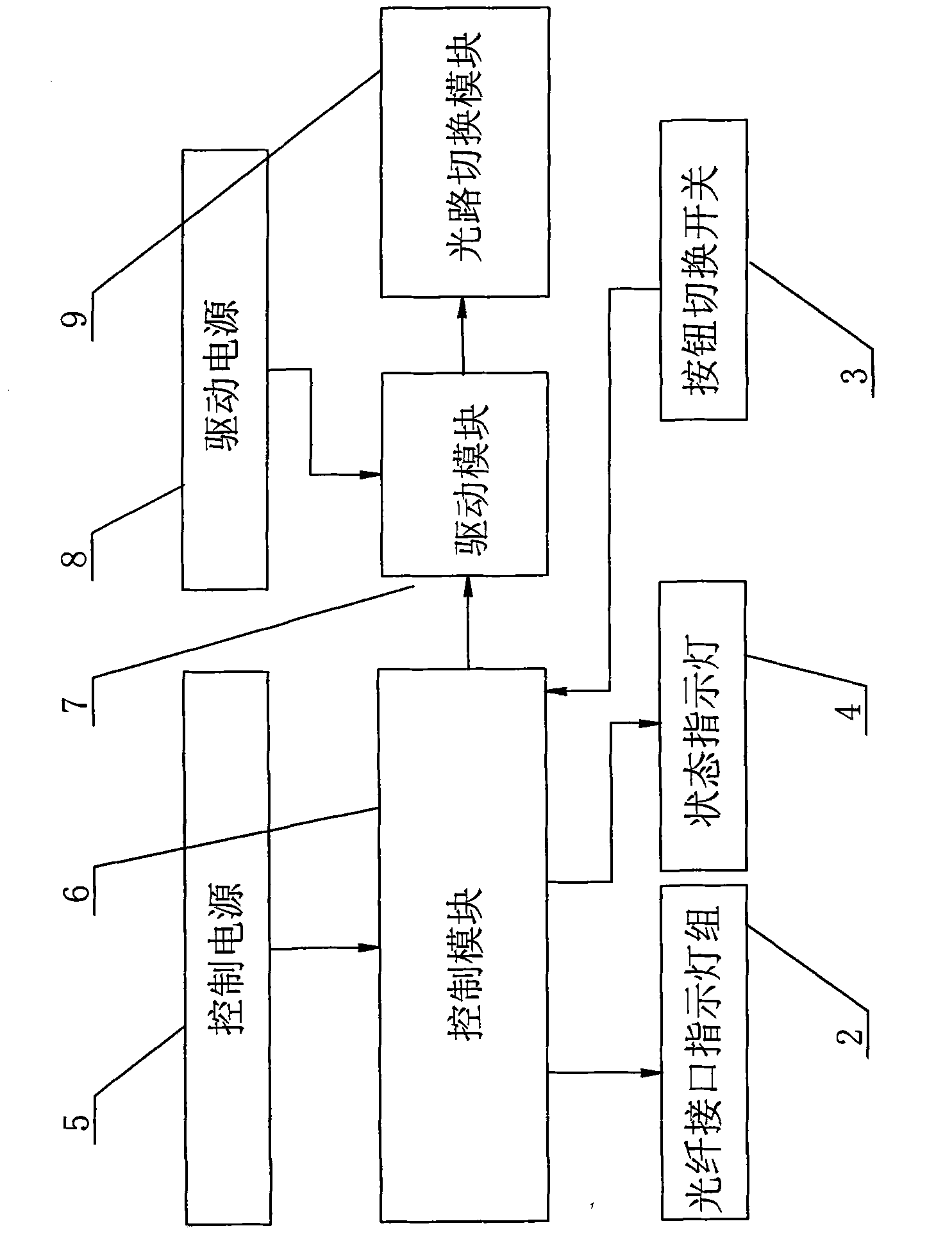
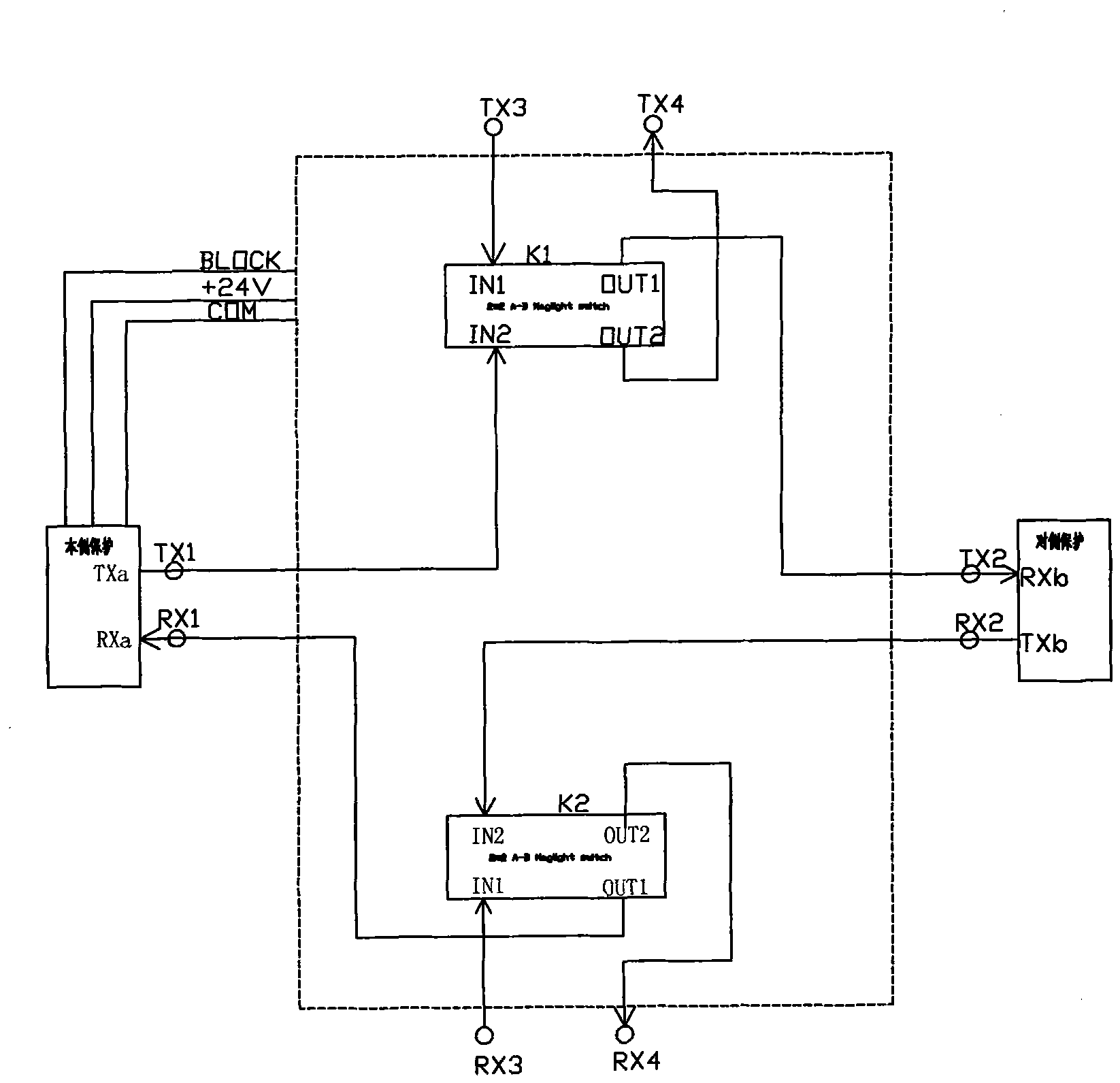
[0012] see Figure 1~3 As shown, the switching optical path interface mechanism for the fiber channel test of the relay protection device of the present invention includes a hood 1 and a control module 6, a drive module 7 and an optical path switching module 9 installed in the hood 1. The control module of the present invention 6 is a complex programmable logic device, which is manufactured by Altera Corporation. The control module 6 is used to provide the switching signal input by the corresponding ON optical path switching module 9, and the power terminal of the control module 6 is connected to the control power supply 5. The control power supply 5 adopts DC24V, and its power consumption is as small as possible. The input terminal of the control module 6 is connected to the button switch 3 in the running state and the test state on the panel of the hood 1. The button switch 3 is in Press again and again to switch between "normal state" and "test state". The input signal of th...
PUM
 Abstract
Description
Claims
Application Information
 - R&D
- Intellectual Property
- Life Sciences
- Materials
- Tech Scout
- Unparalleled Data Quality
- Higher Quality Content
- 60% Fewer Hallucinations
Browse by: Latest US Patents, China's latest patents, Technical Efficacy Thesaurus, Application Domain, Technology Topic, Popular Technical Reports.
© 2025 PatSnap. All rights reserved.Legal|Privacy policy|Modern Slavery Act Transparency Statement|Sitemap|About US| Contact US: help@patsnap.com


