Constant-pressure helium control device of vacuum system and constant-pressure control method

A vacuum system, constant pressure control technology, applied in the direction of electric fluid pressure control, etc., can solve the problems of reduced helium permeability, inability to ensure the stability of helium pressure in the vacuum system, and inability to ensure the helium pressure in the vacuum system, etc. Achieve the effect of high control sensitivity

Active Publication Date: 2011-02-09
WUHAN INST OF PHYSICS & MATHEMATICS CHINESE ACADEMY OF SCI
View PDF5 Cites 8 Cited by
  • Summary
  • Abstract
  • Description
  • Claims
  • Application Information

AI Technical Summary

Problems solved by technology

[0003] At present, the method of injecting high-purity helium into the vacuum system is to inject the helium in the cylinder into the vacuum system by using a filter-type helium micro-leakage valve (also known as helium leak) (see patent CN1479031A). The temperature control of the leak is used to control the penetration rate of helium into the vacuum system. The disadvantage of this method is that when the external environment temperature changes or the pumping rate of the vacuum pump that maintains the vacuum system changes, the pressure of helium in the vacuum system also changes. Changes will occur, and due to the existence of the temperature control system, the helium leak still injects helium into the system at the original permeation rate, so the stability of the helium pressure in the vacuum system cannot be guaranteed
At the same time, because the helium permeability is not only related to the temperature of the helium leak, but also related to the pressure difference of helium on both sides of the helium leak (the greater the pressure difference, the greater the permeability). The difference gradually decreases, the helium permeability decreases, and the helium pressure in the vacuum system decreases accordingly, and the stability of the helium pressure in the vacuum system cannot be guaranteed.

Method used


Image

  • Constant-pressure helium control device of vacuum system and constant-pressure control method
  • Constant-pressure helium control device of vacuum system and constant-pressure control method

Examples


Embodiment Construction

[0017] The present invention will be further described below in conjunction with the accompanying drawings.

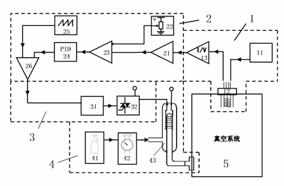
[0018] Depend on figure 1 It can be seen that the vacuum system helium constant pressure control device is composed of signal detection part 1, pulse width modulation signal part 2, power adjustment part 3, helium source 4 and vacuum system 5; signal detection part 1 is composed of vacuum gauge power supply 11, vacuum gauge 12 and a current-voltage conversion circuit 13, the pulse width modulation signal component 2 is composed of a signal amplifier circuit 21, a voltage setting circuit 22, a subtraction circuit 23, a proportional integral differential circuit 24, a sawtooth wave generating circuit 25 and a voltage comparison circuit 26, and the power The adjustment part 3 is composed of a zero-crossing trigger 31 and a triac 32, the helium source 4 is composed of a helium bottle 41, a pressure reducing valve 42 and a helium leak 43; the vacuum gauge 12 is installed on...


PUM


Abstract

The invention discloses a constant-pressure helium controller of a vacuum system. In the device, a helium pressure signal in the vacuum system is measured by using a vacuum gauge, the pressure signal is compared with a set value to generate a feedback signal, the heating power of a filter helium micro-leak valve (hereinafter referred to helium leak, see patent CN1479031A) is adjusted through the feedback signal, and finally the helium pressure of the vacuum system reaches the set value. The device and the method have the advantages that: the pressure signal is directly fed back by using the vacuum gauge, the heating power of a helium leak heating wire is controlled through the feedback signal and the permeability of the helium is adjusted so that the device realizes direct control of the helium pressure in the injection vacuum system and is not affected by environmental temperature, pumping rate of a vacuum pump and helium pressure difference change on two sides of the helium leak; and the controller realizes control of the heating power, namely helium permeability of the helium leak by using pulse width modulation, and has high control sensitivity of the helium pressure in the injection vacuum system.

Description

technical field [0001] The invention relates to the fields of electronic technology and vacuum technology, and more specifically relates to a device and method for injecting constant-pressure helium into a vacuum system, mainly used for injecting constant-pressure helium into the vacuum system. Background technique [0002] In order to study the physical properties of particles such as atoms, molecules or ions, some experiments must be carried out in a vacuum system with an ultra-high vacuum degree. The vacuum system mainly includes a vacuum sealed cavity for opening and sealing and a vacuum gauge for measuring the vacuum degree. In many physical experiments carried out in vacuum, in order to better study the physical properties of particles such as atoms, molecules or ions, it is necessary to cool the particles with higher temperature or thermal kinetic energy. A simple and reliable method is to inject high-purity inert gas-helium into the vacuum system, and reduce the ther...

Claims


Application Information

Patent Timeline
Patent Type & Authority Applications(China)
IPC IPC(8): G05D16/20
Inventor 佘磊杨玉娜柳浩屈万成李交美
Owner WUHAN INST OF PHYSICS & MATHEMATICS CHINESE ACADEMY OF SCI
Why Eureka
Try Eureka